
An evening at ME-QN
- 19 juil. 2020
- 25 min de lecture
It is a great pleasure to publish this article by Sébastien Charlet, a historic member of our association here, so discreet but so passionate about Concorde.
As I take up the pen to clear up the quick notes taken during this incredible evening, a pinch in my heart embraces me. September 14, 1995, so far already...
I was studying History. Volunteer at the Athis-Paray-Aviation museum, on the preproduction Concorde 02, close to my parents' house.
And at that time, passion and curiosity were enough to enter Roissy, in the Concorde / Airbus A310 division.
How did I do it?
A simple letter to the directorate of flight operations after a phone call to find out who to contact, and a few weeks after Mr. Patrick Josseaume, director of engineering of ME-QN, contacted me to invite me to come in his offices.
Second pinch, more bitter: I made a somewhat special trip on Concorde, and I realize today that it was the F-BTSC who offered it to me...
So this Thursday in September, arrived by RER and bus at the end of Roissy-CDG, route de l'Arpenteur, on the Roissy-en-France side and maintenance area.
Phone call to Mr. Josseaume to confirm my arrival, identity card exchanged for a pass at the control booth, and I am told to walk along the employees’ restaurant then the vast esplanade framed by two giant hangars facing each other.
The most distant is the once which houses the Airbus and Concorde divisions, the H3 hangar.

Entering Air France via rue de l'Arpenteur: security pose and parking on the right, then you arrive at hangars 747. To go to QN, you walk along these hangars to the left at the top (Googlemaps 2020).
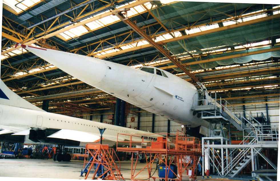
I am warmly welcomed by the members of the Concorde engineering office, within the ME-QN division. It is a vast room of five-six offices, on the first floor of the block of locals flanked at the back of the hangar, which faces the giant doors, with a view of the planes.
At the back of the room, Mr. Josseaume's office; an adjoining room for the secretariat overlooking the access bridge ... at the foot of the stairs leading to it, grilles protecting the spare parts stores. The right hand side of the hangar and the symmetrical offices are the domain of the Airbus A310.

The Air France city: opposite the two 747 hangars, the H3 Airbus / Concorde hangar with white doors, at the top left of the image, then at the top right the A320s. The establishment committee building is at the bottom left, on the side of the 747 hangar (Googlemaps 2020).
I remember very well Michel Delhalle who hardly counted his time to show me around and explain the activities of engineering, of Freddy Mista, Pascal Menegat, Jacques Bruynooghe, all those who kindly told me about an anecdote, who an explanation of their daily life.
The team was divided into the following areas:
- Mr. Delhalle is a fleet engineer expert,
- J. Bruynooghe takes care of avionics with Yves Linder,
- F. Mista the structure,
- D. Guingand hydraulics,
- P.Menegat propulsion,
- J.M Picard cabin systems.
What is engineering, exactly?
A team of experienced technicians, most often from the hangar, who are at the same time perfect connoisseurs of the aircraft and of daily procedures and gestures. They are responsible for analyzing the glitches occurring in operation and for writing intervention sheets.
At the same time very clear and very precise, for the use of mechanics having to intervene in maintenance on Concorde, these kitchen files were also called "check-lists", a nod to the flight crews.
The engineering does the interface between Air France, the manufacturers and the regulatory authorities. Its experts go back and forth between the maintenance procedures set by the manufacturers and the vagaries and needs of operations, small and large maintenance.
QN also had a rare specificity: it itself carried out major Concorde visits, where the 747s departed for that to Orly.
Engineering communicates permanently with Aerospatiale and British Aerospace, with DGAC (France), CAA (UK) and FAA (USA), to improve maintenance procedures, receive modifications decided by manufacturers, validate solutions designed at Air France.
Rigor and security, always.

An example of a "checklist": here how to inspect a used tire and determine if it should be changed.
I keep the memory of a studious, modest and cordial team. I still have in mind the two large cabinets containing the tens of linear meters of manufacturers' Concorde maintenance method filing cabinets...
The discussions were going well, with comparisons full of surprise between the preproduction 02, on which I was a volunteer at home, in Athis-Mons, and the production machines; my questions on the site then, namely adaptation of a TCAS system requested by the FAA for Concorde.
The difficulty was to certify the transceiver antenna in the hot environment of the supersonic cruise ... And these observations of Mr. Delhalle: "the more it flies, the less it breaks down. It is kind of the last steam locomotive ", in order to illustrate the demanding complexity of the Company's standard bearer.
The availability of my hosts is a pleasant surprise.

ME-QN in 1996: in front of Concorde the store of specific parts.On the right, the offices. At the back of the hangar, section A 310(Coll. S. Charlet 1997).
I spend the second part of the afternoon walking around the hangar around the F-BTSC on maintenance, taking pictures here and there at the whim of the mechanical parts open to the open air.
The rule is simple: I ask if I disturb and if I can observe. I have never been ask to get away, my discretion always seeming to serve as a passport.
I had received all the green light, on the express condition - and so obvious in my opinion - not to touch anything. Another era, I tell you...
I was never taken from high, kindness was there at each of my meetings, to believe that each had given the word!

To the right of Concorde: downstairs, the team planning and rest rooms.Above the parts stores (Coll. A. Jolivet 2003).
Some technicians are browsing the SC, all on their work schedule. The atmosphere is calm, everyone knows exactly what to do.
Driven by curiosity to see a complete and "living" Concorde, I was able to sit in the right seat of the cockpit.
Why "alive"?
I already had the insignia chance of helping to restore Concorde 02. But this one in 1995 was an extinct and very incomplete machine, degraded by many years of disinterest, before being saved and restored by the association Athis-Paray Aviation near Orly.
Here, everything lights up, it vibrates: no smell of bakelite, metal and electronic components like in museums, but that of new carpet…
It is 6:00 p.m., which is confirmed by a mechanic who tells me that we will have to leave the board.
The F-BTSC in which we are, will leave the hangar for a fixed point, and the teams will themselves go to dinner in the canteen.
An engine bench test session is scheduled for this September evening.
I do not know what in my expression could have put them in the ear, or was it the rarity of a "civilian" visitor at the heart of their meticulous activities?
Maybe my questions a little too specific about their work? Still, I am surprised to be asked:
- "Do you want to accompany us and attend the fixed point?
- It's possible?
- Of course.
- And you come to dinner with us?
I'm not sulking my luck!
So here I am around 7 p.m. in the canteen of the Materiel Department, a medium-sized building of the establishment's comity.
At this hour, quite few people, because it is the evening teams who take their meals.
A classic but consistent meal, a conversation based on family news and what I could have done to get so interested in Concorde and Air France.
ME-QN en 1996 (Coll. S.Charlet)
Things get serious soon after.
Back to hangar H3: the team for this evening takes me to a large glass room located in the hangar, between two spans and therefore two planes. It is the haunt of mechanics and controllers: large tables on which large mass plans are unwound, diagrams, schedules and load plans ordering the succession of work, a plethora of filing cabinets, telephones, telex and fax.
Two controllers arrive at the Controller General, who has just taken over at around 7.45 p.m.
It is the eldest of this small assembly, Jean-Jacques Chillaud, who will chair the session.
We check by radio that we have requested a tractor to take the SC, because the fixed point was originally scheduled for 7:30 p.m.
The team splits up, some spinning in a 4L to follow the tractor, the controllers offering to go back up in SC.
I put myself in the right place at the station, the controller in the left place.
As far as I can remember, two other mechanics went up, one of whom was at the flight engineer station (OMN).
SC is shaking, and we make the patient and trembling travel towards the area of fixed point, behind the giant hangar of 747.

My one and only trip on Concorde, a real one!
But without leaving the ground...
I'll be happy with that.
I could see thereafter the rarity of testimonies on Maintenance, behind the scenes of an airline company, forgotten testimonies...
Suddenly, the not-so-crazy idea comes to me to take paper and write down everything I can understand. At the time I was relentless: I started in college, bad at math I was, by wanting to understand the functioning of a Concorde...
I started with a Concorde station flight narrative written by Marc Alidieres and Philippe Renault air traffic controller, published in a DGAC review. A rough introduction to the jargon of flight crews! But tonight, it's my turn to stick to it.
What a unique feeling to be so high up, already so far from men without having left the ground.
I am not perched on a scaffold but on a comfortable armchair, facing a complex set of instruments. The journey is not very long, and leads us on the right side of the hangar of the 747, to a concrete esplanade of good size, occupied by two concrete tubes whose ends curve towards the sky: the noise attenuators.
It is eight o'clock. The test session must take place from 8:30 p.m. to 10 p.m. I stay in the right seat, guest of honour because no command will have to be used on my side.
Jean-Jacques Chillaud orders the test in the left seat.
At 8:05 p.m., authorization for a fixed point was requested at the control tower, for the F-BTSC aircraft, Foxway 13, from 8:30 p.m.
Now the technical observations will be released in the narrow cockpit.
We checked: the magnetic plugs of the engine oil circuit, the level of the yellow hydraulic tank (with its 6.5 US gallons pumped by hand due to the lack of a working electrical outlet, from what I understand The oil gauges of reactors 1 and 2 are checked, and there is an additional level to perform, we observe.
I stealthily note the program: verification of the Primary Nozzle Control on reactor 4; warm-up test on 3; an air conditioning test on 2, due to a dark history according to which the low pressure air conditioning gauges can break the brakes (the manometer of the brake module, the one of the warning light BKES FAIL) in simultaneously sending a brake release signal, despite the brake delay. Something happened on the F-BVFA on September 12 during taxiing...
Did I understand all the terms on this list?
So would this be a joker electrical relay to examine?
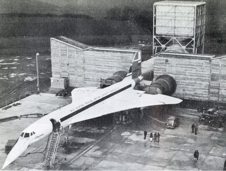
Concorde fixed point views are not so common. To illustrate those of Roissy, we had to take that of Concorde 001 in 1968 in Toulouse, in the same configuration (in Diagrams of the world, November 19, 1968).

The Roissy CDG fixed point area and noise attenuators (coll. A.Jolivet, 2003).
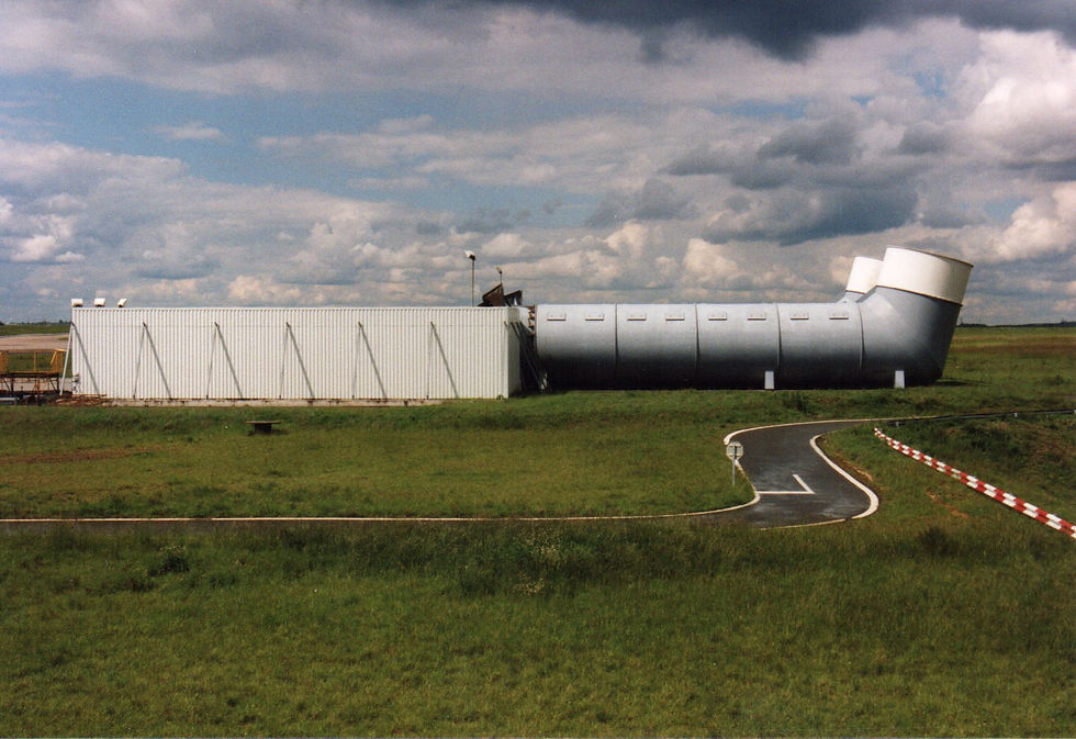
Concorde noise can be compared to that of a military aircraft, and a device is required to attenuate noise from tests. We place the plane, wedges in place so that it does not move from its position, because we will apply the thrust and the machine should not move! The nozzles open into the attenuator which breaks much of the noise from the shearing of hot gases in the ambient air.

Opposite: in place for the fixed point. The very high accommodation ladder is on the right; to the left of the image a stepladder to connect the park socket which supplies the power to the aircraft when the engines are off. And at the foot of the stepladder, the white block of the generator providing the 115V / 400Hz (Coll. A.Jolivet, 2003).
We descend to the fixed point area. We check that the wheels are locked, the brakes are applied and in good condition, as well as the air intakes, the belly of the device.
It is necessary to make sure that no tool has been forgotten, even if every good mechanic counts the number of tools he has when getting on the plane, and recounts them when he leaves.
Checks, always ...
Similarly, there must be no objects on the ground, near the air inlets that can be sucked.
Two air starters are connected. The visit is made from left to right. Finally, we visit the silencer on the right if it is clean of all debris. The cargo hatch is closed. Two mechanics finish filling the oil tanks by hand on the 3 and 4. In the background, the hiss of the pneumatic group, and the sound of diesel, that of the 115-volt park group.
We take our places; it is 8:25 p.m. on the on-board watch.
Before me the co-pilot's navigation board, useless this evening. Between the two pilots, the "primary" engine controls, overlooked by the engine indicator panel. Prominent, the throttles control the operating speed and therefore the thrust.
The flight engineer behind us is in charge of the "secondary" commands, that is to say the numerous switches and selectors of the electronic regulators which allow the pilots to have the desired thrust at the end of the throttles.
There are five vital instruments for the crew.
Their abstruse names will bring back memories to some, and will resemble the gibberish of the doctors of Molière for the others. And that's what they are, in both directions: parameters of life, of good health of this complex machine which sucks, compresses, expands and expels air by vibrating, heating, sucking and expelling oil and fuel.
We therefore distinguish:
a) N1 is the speed in percentage of maximum continuous speed of the Low Pressure compressor, which is the first to suck in air from outside; he turns more slowly than his brother who turns after him, so as not to gasp while swallowing the air packets sucked in by the air intake. The air is crushed there, compressed by the blades at three times its intake pressure. 6500 revolutions per minute give 100% N1.
b) N2 designates the High Pressure compressor, which rotates faster and compresses five times the air that its brother brings it upstream. 8,500 revolutions per minute give 100% N2. In the end the air is compressed to 15 times atmospheric pressure (since we are on the ground).
c) EGT or, “Exhaust Gas Temperature”, designates the temperature of the gas flow after the turbine. It is the most important parameter of the health of the engine, it indicates if the engine is started, and if combustion occurs within the specified standards.
d) The FF or Fuel flow is the consumption in tonnes per hour.
e) We will see the 5th parameter, noted "AREA" after a useful description of the engine…

Above: the central panel and the engine gauges (from top to bottom):N2, N1, FUEL (flow), EGT and AREA (or Aj).(photo Donald Morrisson).
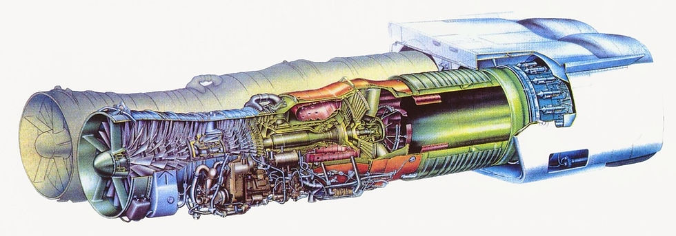
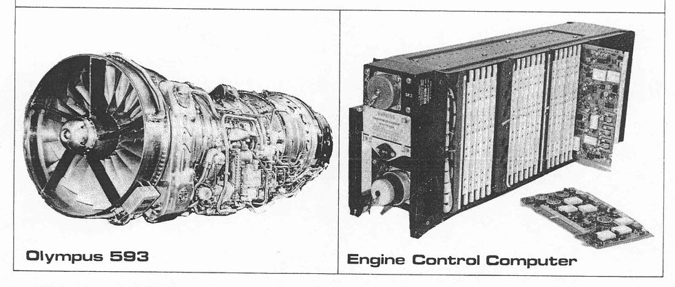
The Olympus 593 is an engine of an old but original design, which was pushed to the limits of art by the very fine know-how of the people of Bristol-Siddeley (then Rolls-Royce). It is the first engine in the world to have a double body (or double hitch): it has two axial compressors, each driven by its own turbine. Above, the series version, known as "610" with its secondary eyelid-shaped nozzle (SNECMA image, 1973).
Below, an exploded exploded view below concerns a 539-3B engine of prototypes 001 and 002, with a final nozzle (called secondary nozzle) in petals, similar to fighter planes

The Concorde engines have a fairly simple architecture but a complex and original operation. Conventionally, an Olympus is supplied with air by two compressors, each driven by its own turbine. Also, there are, from front to back: a Low Pressure compressor (BP) which performs the first part of the compression work, then a High Pressure compressor (HP) which completes this work. The combustion chambers are thus powerfully supplied, and the rise in temperature due to the chemical combustion of kerosene allows a very powerful expansion of the gases towards the rear. These hot gases relax by printing their pressure on two turbines, which themselves drive the compressors upstream, by means of two metal shafts embedded one inside the other. In this way, the engine supplies itself with air.

This sectional diagram of a 1969 Rolls-Royce course highlights the two concentric shafts which connect the compressors to their respective turbines.Note: the gases exit through the "primary nozzle" or mobile primary nozzle which opens or partially closes.
.
Like fighter planes, these gases exit through a petal nozzle, called the primary nozzle, whose role is crucial. Like a flower, it opens more or less to vary its exit surface, and controls the speed of exit of the gases. When the speed of the compressors increases, the suction flow does the same, and the mass of propellant gases increases, so the nozzle must open more to release this kinetic energy. It is buried in the middle of the long nozzle of the engine, and from outside, the spectator notices only the two half-shells of the secondary nozzle, in dark gray steel.

At the Imperial War Museum in Duxford, at the foot of Concorde 01: a rare view of the primary nozzle, usually embedded in the hull that supports the secondary nozzle (the "eyelids"). We can distinguish the crown of metallic petals, each pair of which is operated by small cylinders (DR).
Our two compressors are controlled differently, although this is transparent to the crew who only have to handle the throttles to measure the thrust.
Here's how.
The throttles, like the accelerator in a car, control the amount of fuel and therefore the thermal energy that will accelerate the air flow from the reactor (and the speed of our plane). By pushing the levers forward, we admit more kerosene, our flame becomes stronger, the hotter gases drive the HP turbine and its compressor faster. The HP speed, known as “N2”, is increasing. As the accelerator pedal makes your car engine run faster.
But at the inlet of the reactor, the BP compressor behaves like a turbocharger: it can adjust its rotation speed called "N1", therefore its air absorption capacity, more or less quickly compared to its brother in downstream. The low-pressure compressor optimally adjusts the supply of his brother, who can only absorb air that is already very compressed. Little known tip, it is the primary nozzle close to the exhaust, which by opening or closing, controls the speed of the "turbo" compressor. In technical language, the N1 and N2 regimes can be controlled separately.

A rare view in section, with the same order: the LP compressor (1), the HP compressor (2), the combustion chambers (3), then the HP turbine and BP turbine (4), reat rings (5), reheat channel, primary nozzle (6) then secondary nozzle (7), which does not interest us in the procedure of this story but plays (among others) an essential role in cruise (SNECMA-Musée Safran).
It is a little-known point of the Olympus. Although driven by the same gas flow, it is possible to rotate the two turbines at slightly different values, one independently of the other.
Why?
The hot flow becomes sonic (it reaches the speed of sound) at the stator vanes, and shock waves are formed there. These waves make it possible to separate two different pressure zones, one in which the HP turbine turns, the other the BP turbine.
The pressure of the gases pushing on the HP turbine depends on the fuel injected, but the pressure pushing on the BP turbine depends on the primary nozzle which acts as a bottleneck. When opening or closing, it "stuffs" the exhaust flow, like your fingers pinching the garden hose outlet to reveal a leak upstream on the tube! The nozzle closes, the pressure rises, the turbine is supported by denser air so it rotates more slowly: the N1 decreases...
If you've managed to follow so far, you're ready for the next Concorde remedial training!
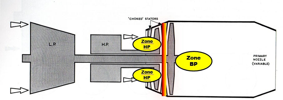
"Choked stator" is the English expression which indicates shock waves occur at the level of the fixed blades of turbine. These waves form a border between a pressure zone in which the HP turbine rotates, and another zone where the BP turbine rotates. The orange line is here only to represent the pressure barrier which separates the two working areas of the turbines (image Rolls-Royce and S.Charlet).
It is here that the 5th vital parameter appears, the Aj: "A" for "AREA" or area, and "j" for "jetpipe" or nozzle. The AJ indicates the opening section of the primary nozzle, in a way the narrowness of the gas outlet passage.
An electronic computer finely controls our primary nozzle-compressor BP chain. It is called "Throttle Control Unit", or TCU, it manages kerosene and the primary nozzle. It’s precisely his electrical signals that are drawing the attention of QN’s men tonight.
We are therefore focusing this evening on the Aj dials which indicate the opening at the appropriate time of this primary nozzle!
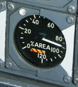
Right: the AREA dial. The more the nozzle opens to release the higher the percentage indicated (100%).The small white lamp indicates that the heater is armed: when putting in the gas, when the engine exceeds 81%, the computer injects fuel to light the heater flame.The white sector indicates the range of nozzle opening in which the heater operates.
We can now reason like our technicians:
- We put the gas: large Aj, wide open = large N1!
- We reduce: Aj weak, small passage = small N1!

Object lesson: an unusual view of the eyelids of the secondary nozzle… disassembled! The upper eyelids are in revision, the lower ones have their thermal shield removed. We can see a half-serrated corolla in the darkness; it is the primary nozzle (coll. S. Charles, 1997).
At 8:27 p.m., request for start authorization for the fixed point, on 121.60 MHz, granted immediately.
The cockpit is full, two controllers, three mechanics spectators of DM.QR, and myself. The manager fills in the statement sheet.
At 8:28 p.m., he checked through the intercom to see if everything was good on the ground, and the gangway was moved back 1.5 meters.
The electric pumps are plugged in Green / Yellow: motors off, these do not drive their alternators or their hydraulic pumps. The ground electrical group must supply the on-board network, and then two electric pumps are started to have hydraulic pressure. "Green" is the code name for the main hydraulic circuit, the largest because the one that actuates the flight controls, landing gear, air intakes. The "blue" circuit is the other, smaller, main circuit dedicated to flight controls. And the "yellow" is its twin intended to take over in the event of a breakdown or a drop in pressure.
This color code is a distant reminder of the De Havilland Comet of 1949, for which it was invented! Which was then picked up on Caravelle, and taken back to Concorde.
The mechanic manually raises all the air inlet ramps (I note a rapid movement of the order of 10 to 15 ° per second). Controller and mechanics do their checks, their checklist like seafarers.

8:29 p.m .: the starter group posted on the ground near the engines, connected to the right engine nacelle, sends pressurized air into the right pneumatic circuit, intended for cabin air conditioning and the air starter.
8:30 p.m .: we're ready for engine 3.
From now on, everything that follows responds to a coded litany, fast and precise.
The mechanic in place F/E opens the start valve and announces: "open N2. Start Pump. " The compressed air is sent through the small turbine of a starter, which drives the high pressure compressor, which our mechanic notes verbally when he sees a small magnetic indicator go white and a yellow warning light comes on. This is the "Start pump", which is another pump which sends the kerosene to start injectors located in the combustion chamber.
On our side, we see the small white needle of N2 rising to 10%: the reactor has taken a minimum of momentum and air suction to start.

The mechanic station on the F-BTSD: located on the left knee, the start control panel which includes the start air valve opening switches, the rotators to select the igniters (coll. S.Charlet).
J.-J. Chillaud announces "HP" by opening the high pressure valve which admits kerosene to the main injectors, at the heart of the reactor. At the same time a high-energy box releases a high-voltage current which lights a spark plug, which ignites the vaporized fuel. It's ignition, which takes a handful of seconds. The equipment must count 8 seconds and note the packaging in this interval.
F/E announces that it sees the yellow indicator light on the left high-energy box light up, and J.-J. Chillaud announces "EGT" when it sees the temperature indicator go up: there is a flame in the reactor !
I note about 200 ° C, then that the speed of the high pressure compressor, the N2 stabilizes at 30%, with the N1 at 16%.

Right: the EGT indicator: prohibition to pass 730 ° C!The yellow lamp indicates that the engine control computer is no longer receiving temperature information.
The start panel (detail on the previous page):

- Magnetic indicators for opening the starting air valve (supplies the air starter).
- Start selectors: the start valve is opened in the "START" position.
- Stalking selectors: in the "DEBOW" position, the TCU maintains the speed at 30% for one minute. The integrated yellow light comes on to tell OMN to switch to "NORMAL". The engine then goes to its normal idle speed of 62%.
- On the left, the selector switch for the High Energy boxes and their spark plug: LH for the left candle, RH for the right, BOTH for both simultaneously
(photo S.Charlet).
Concorde has spark plugs! (Rolls-Royce 1976)

Particularity of Concorde: one must carry out a “debow” when the engine is not completely cold, nor entirely hot. Indeed, the Olympus engine is distinguished among other things by its length. The air-sucking compressors are driven by their respective impellers by means of long hollow metal shafts. However, these "tubes" do not heat up homogeneously at start-up: in other words they do not rise in temperature evenly over their entire length ... therefore they expand in certain places but not others, and are burdened with a "Unbalance", or an unbalanced mass which in turning, vibrates and wears the motor shafts So we grant the engine to run at a low idle of 30% so that the internal shafts warm up without forcing.
The military predecessor of the Olympus 593, the Olympus Mk 320 designed for the BAC TSR2 bomber, had revealed the difficulties of very large connecting shafts between compressors and turbines. Although smaller, it reacted to vibrational phenomena by exploding! The shafts were breaking at very high speed. A Vulcan test bench bomber burned to the ground in 1963; three other engines exploded on a test bench, the last volatilizing a building in December 1964...
The Olympus 593 did not experience this problem, but it keeps in its "genes" this small requirement for progressive heating...
After a minute, the electronic controller let the Olympus stabilize at its normal idle speed, 62%, and the crew announced it to colleagues on the ground. I then hear a low hiss coming from the rear, when the N2 accelerates beyond 50%.
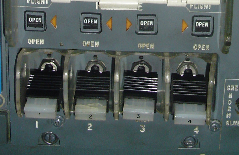
Au plafond, les interrupteurs de robinets Haute Pression: de forme rectangulaire, ils comportent une lampe rouge qui On the ceiling, the high pressure valve switches: rectangular in shape, they include a red lamp which lights up in the event of fire or overheating. They are the ones that open the arrival of kerosene to the injectors in the combustion chamber. We find the magnetic indicators indicating the opening by "OPEN" (coll. S.Charlet).
The engine 4 is sent at 8:31 p.m .: top open, N2 at 10%, J.J. Chillaud calls "HP" by opening the HP valve. The mechanic announces ignition, J.J. Chillaud "EGT" when the temperature takes off; it rises to 300 ° C. On this engine today, the N2 rises very slowly. "It may have lost the starting air," we observe. When calling J.J. Chillaud "25%", we decide to keep the start valve open, while in normal times the automation cuts the valve and the spark plugs. Waiting. We go into normal mode, slowed down to 62%: it is only 20 hours 32 and 30 seconds ... The external air supply is cut off on the right.
What to take away from this moment?
The maintenance people adapt to any situation and, like a doctor, capture all the symptoms of the machine.

Extremely rare photo of an Air France Concorde at a fixed point, taken by A.Jolivet in 2003: night, arrangement, actors, everything is identical to my evening in 1996. Here the engines are off and we are working on an organ internal motor. The men in blue from Maintenance wear the reflective vest. It is easy to guess that the jet of gas from the reactors is swallowed by the cavity of the attenuator. Note the blackening of its walls!
Engines 3 and 4 at idle display:
N2 66% 64%
N1 41% 38.5%
EGT 450 ° C 455 ° C
FF 11 10.5
P7 21.05 21.5
Aj 87 91
P7 is a 6th parameter monitored by the F/E; it indicates in psi the pressure which reigns in the nozzle.

The coloured indicators on the side indicate which hydraulic circuits are pressurized by the engine of this dial (green and yellow).
A personal reflection: in these moments of concentration, the time felt expands, so much so that in so few minutes so much has been done and observed...
Each gesture is perfectly reflected, since we have just lit behind us a huge "blow lamp"...
The "men in blue" handle an expensive machine with calm and method, just like the sailors.
It's time to put engine 4 to the test! It is the first power-up.
At 8:34 pm and thirty seconds, Jean-Jacques Chillaud pushes the joystick of 4. According to the test procedure set by Rolls-Royce, you must stay one minute maximum allowed, or 104%.
A minute later, we are at 102%, and I notice dumbfounded that the device kicks, squirms from the back like an eel!
We continue: at 36 minutes,
N2 reaches 103.5%,
N1 96%,
F / F 11.15 tonnes / hour,
EGT at 763 ° C,
Aj at 43%.
We stick to it, the chef's gaze oscillating between the chronometer and the panel of the engine gauges.
At 37, the time passed, an acolyte in the corridor of the computers indicates that he has obtained the parameter "82" on the dial of his test case. The maintenance manual specifies that the electrical signal that the computer sends to its engine must be picked up, to verify that it is at the correct value. If necessary, the controller adjusts it. We estimate the correct setting, and we agree not to repeat the test.

Found in a Rolls-Royce course, what I believe to be the box used that evening to control the pneumatic valve which doses the air admitted into the jacks controlling the petals of primary nozzle ... The elders will be able to correct me! It is connected to the control amplifier, the Throttle Control Unit, which is located in the station access corridor. The dial indicates the value of the control signal sent to a pneumatic valve, the PNC, which controls the opening or closing of the nozzle.
However, J.J. Chillaud deems it relevant to tickle the engine again, because barely thirty seconds later, he quickly pushes the joystick of the 4. At 99% of N2 there is a big swerve forward, and the N2 seems at this moment precise as stuck, the dial hand stops, to finally free itself and go to 102%. Our fourth boiler seems finicky, despite this first adjustment of its control box, the "Throttle Control Unit".
Crazy detail, I get water on my face ... condensation from the aerator on the ceiling?
It is 8:39 pm. Engine 3!
The yellow hydraulic pressure is sent and rises regularly, slowly. The cockpit is smelled of petrol...
At 40, reheating is armed, a white lamp lit on the Aj dial of 3. The primary nozzle must first close slightly to establish a pressure suitable for stabilizing the reheating flame, then open fully.
We push our controller. The N2 rises and blocks at 99%, RHT ("Reheat", for reheating) on, Aj at 15% and which does not open as it should. We try a second test: the N2 is pushed to 105%, and there is no blockage, with an Aj at 80%.
The second control amplifier of motor 3 is selected, to check whether it is not the main unit which would send erroneous signals.
But no. There is a delay in opening the nozzle with the two housings, and this designates the PNC valve as being faulty: it is it which obeys badly. The Primary Nozzle Control Valve is the valve that controls the small cylinders of the nozzle petals.
The test of motor 3 is completed.
The work program remains dense: engine 2 must be started to check the air conditioning. The litany resumes at 8:43 pm. I note that the temperature stabilizes at 210 ° C. By cons I see nothing of the manipulations made on this engine; behind us other men are at work.
Below: the indicator for N1: the orange lamp indicates a problem of adaptation of the low pressure compressor in supersonic flight.

But J.J. Chillaud is still not satisfied with the reactions of the 4. The torture resumes, but this time you have to check its behavior with the reheat on.
At 8:46 p.m., reheat on the 4th is requested, and the engine is this time slowly mounted. We want to meticulously observe the reactions of the engine ... Its N2 passes 102%, but SC swerves, then the counter goes down to 100%. The 4 is still blocked: the AJ does not react well. Specialists can observe that at the time I was obsessed with the N2 dial ... while I explained before it was N1 and Aj who are leading the way! I understood many readings later.
Behind us however, the mechanic sends the green hydraulic pressure. Witness, in front of my knees the pilot yoke rises about ten centimeters towards me.
A "clack" is heard under the floor, in the depths of the wheelhouses of control...
The touch of the controls is sensitive and precise, but I only allow myself a few centimeters of travel. The outside team is far from the control surfaces, but do not play.

April 2003: striking view of the heater on engine 1. We can see the orange sonic rings in the white-blue flow, which indicate that it has exceeded the speed of sound. For outside personnel, even helmets, the experience of switching to maximum power can be traumatic, because of the low frequency noise waves which reach the viscera. Headaches and nausea are not uncommon (coll. A. Jolivet).
8:51 p.m., the team gave a mechanical break by shutting down all the engines.
8:53 pm, we turn on the 3.
The atmosphere, punctuated by big jokes is both playful and studious. Outside, it's been raining for a good quarter of an hour.
8:54 p.m., engine 4 is restarted, and I have fun timing everything:
Top start: "open" announced by the F/E.
+ 3 sec: N2 at 15%, "N2" announced by J.J. Chillaud.
+ 7 sec: High Pressure tap controlled opened by the J.J. Chillaud.
The EGT temperature this time does not rise. Chillaud counted mentally for an additional 4-5 seconds, cutting the HP valve. The mechanic switches the spark plug control selector to BOTH, which means that two spark plugs are used to have the best chance of igniting the kerosene. We let another 5-6 seconds pass. The purpose of this maneuver is to save a sequence, the compressor is left running without cutting everything: Chillaud wants to control the operation of the main control amplifier (the "MAIN" TCU). Each reactor is controlled by two identical boxes, a main "MAIN" and an auxiliary "ALTERNATE", one taking over from the other in the event of a failure.
+ 15 sec: EGT takes off and calls.
+ 22 sec: 25% of N2.
+ 30 sec: N2 at 30%, debow.
+ 50 sec: starting air cut off.
+ 1 min 55: normal idle on 4.
+ 2 min 20: 65% of N2, 90% of Aj.
From an advertisement, the Throttle Control Unit, or gas control amplifier… It was for the time an analogic calculation unit at the forefront of electronics. At the rate of two for four engines, they are stored in the corridor which leads to the cockpit, after the front galley (Rolls-Royce).
8:58 p.m., full throttle for the 4th: at 99% the AJ wants to drop from 40 to 20%, so closes, but stumbles on the 20%, bounces and goes to 40% so that the N2 goes to 104%...
The PNC does its own, we comment. The team seems undecided: the nozzle does not open normally, but with a delay.
This means that you will have to be careful to control the TCU control boxes which send the electrical signals, and the valve which should obey them.
At 9 p.m., the reactor is pushed once more to 96%, and the AJ bounces again on 20% as before.
.
"Aren't you afraid of pumping?" I ask.
My neighbor replied: "We don't break a reactor by pumping here.
On the other hand, Air France has had pumping of air intake" ... That is to say in flight. This is another rare problem which theoretically does not damage the engines.
9:03 p.m., the session is over. We now know that there are suspicious organs that will be dismantled for revision, in a workshop in Orly-Nord.
The engines are off for good.
The hydraulic pressure is released by putting the hydraulic pumps on "on" while the latter are no longer driven by the motors: two swerves are obtained in the body of the aircraft.
The team inspects the air inlets, left and right.
It will be necessary to check visually the famous PNC valve, housed in the engine nacelle, all against the nozzle.
It will be done in the hangar, because at this time, we can’t see a drop.
The rain has stopped, but the SC is dripping with water.
He must be in reserve for Saturday and it is Thursday, so there is still work for the men in blue.
When I go back to the security booth and then on the bus, my head is elsewhere.
- I lived a moment rarely offered to a layman.
- And all these discussions…
- What skill!
- What passion and kindness!
- I was able to enter professionals dedicated to their profession, while simplicity but always demanding.
Certainly my "trip" in Concorde was not supersonic.
The fact remains ... unique.
Thank you ME-QN, thank you Maintenance.
Special thanks to Laurent D. for his proofreading of the translation.


Commentaires