
ATA 70-80 PROPELLANT UNIT. Part 7
- 8 août 2025
- 6 min de lecture
And finally, here is the last article dedicated to the powerplant: the OLYMPUS jet engine.
In 1948, BRISTOL SIDDELEY ENGINES was responsible for the world's first jet engine equipped with two independent compressors and two rotors rotating at different rotational speeds.
This BRISTOL twin-spool, single-flow jet engine with reheat was finaly developed starting in 1966 in cooperation by ROLLS-ROYCE and SCECMA and served as the basis for the Concorde jet engine.
In the program, Snecma was responsible for the design and construction of the reheat and the variable-section convergent nozzle exhaust duct, as well as the thrust reverser. It contributed its expertise acquired with the various versions of the Mirage III and IV jet engines.

Concorde will be equipped with four ROLLS-ROYCE/SNECMA Olympus 593-610 engines, grouped in pairs in two nacelles under the wing, developing a gross thrust of 14,700 kg dry, and 17,400 kg with reheat.
This engine is a conventional subsonic engine; it requires the air intake regulation discussed in Part 4, which ensures that the air speed reaching the engine does not exceed Mach 0.5. This is also the case with the articles in Parts 5 and 6, which, along with the engine, make up the entire powerplant. The aircraft's propulsion system allows Concorde to reach a speed of Mach 2.02.
The Olympus 593 Mk.610 engine is a straight flow, twin spool turbojet engine of pressure ratio 15:1 at maximum design compressor rotational speed. The two compressors, low pressure (L.P.) and high pressure (H.P.), are arranged in tandem. Compressors are of the axial flow type, each having seven stages of compression. Each compressor is driven by a single turbine stage.
The role of jet engines is to provide the thrust needed to propel the aircraft. In addition, jet engines provide the mechanical drive for ancillary equipment and deliver the pneumatic power needed for various services.
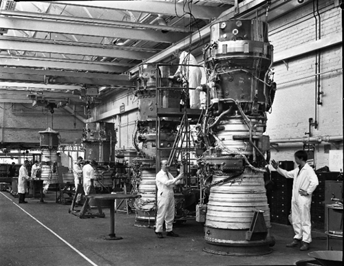

Autopsy of an Olympus
(This article is based on Air France and Rolls Royce training documentation).
The engine is of modular construction.

The characteristic stages of this reactor are:

Station 1 : L.P. compressor inlet.
Station 2 : L.P. compressor outlet, H.P. compressor inlet.
Station 3 : H.P. compressor outlet.
Station 4 : Combustion chamber outlet.
Station 5 : Located after the H.P. turbine.
Station 6 : After the stator between the turbines.
Station 7 : Located in the exhaust duct.
Here are the main parts that compose it in a few drawings:
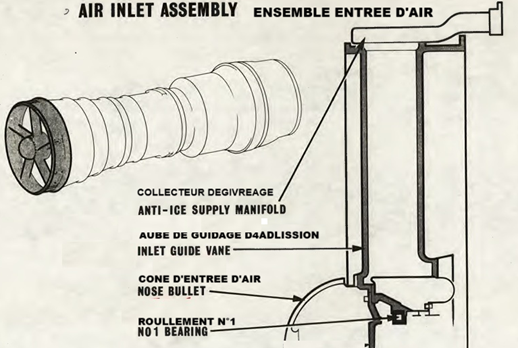
The annular air inlet.
Air intake assembly.
This assembly constitutes the conduit through which air, supplied by the air intake, enters t he low-pressure (LP) compressor.
Made of titanium alloy, it is made from two casings connected by five hollow arms welded at the ends, supporting the housing for bearing No. 1 and forming "pre-rotation" vanes. All arms can be defrosted by air from P3, and arms Nos. 3 and 4 allow the passage of pressure and oil recovery pipes for bearing No. 1.
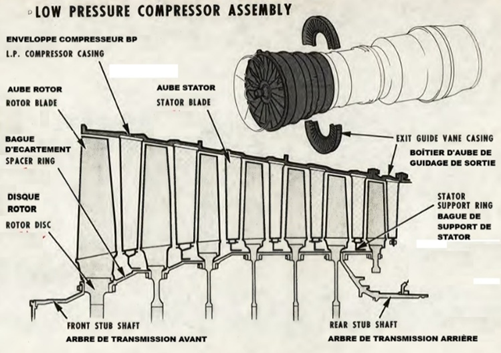
The seven-stage low pressure (LP) compressor.
The LP compressor is a seven-stage axial compressor with a pressure ratio of 3:1. It consists of two main components: the casing and the rotor. Six rows of titanium stator blades are housed in the compressor casing.
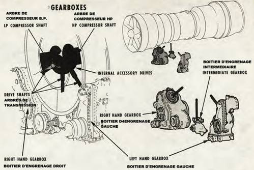
The intermediate case area where the drives and gearboxes of the L and R accessories are housed.
The intermediate casing assembly consists of anouter and inner casing through which passes the L.P. compressor delivery air to the high pressure compressor inlet. The inner and outer casings are spaced by six aerofoil shaped vanes, the whole being manufactured in tinanium. Diagram.
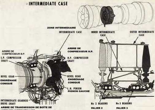
Gearboxes:
Two accessory relays are mounted on either side of the lower part of the intermediate housing, both driven by the HP shaft.
The right accessory relay drives:
- The alternator with integrated CSD.
- Two hydraulic pumps for engines 2 and 4.
- A single hydraulic pump for engines 1 and 3.
- The air starter.
The left accessory relay drives:
- All engine-specific systems.
The intermediate accessory relay:
- Pulse sensor.
- Engine oil pressure switch.
- Engine oil pressure sender.
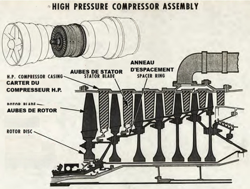
The seven-stage high-pressure (HP) compressor :
The high-pressure (HP) compressor receives its air from the low-pressure compressor via the intermediate casing. The compressor then works on this air, significantly increasing its pressure.
This HP compressor is a seven-stage axial compressor with a pressure ratio of 5:1. The assembly consists of two main components: the compressor casing and the rotor.
The air bleed area for the various pneumatic services.
The air bleeds for external services are :
- P2 air, to drive the fuel turbopump (2nd-stage pump),
- P2 air, is taken from the 5th-stage HP compressor, used to supply the reheat injector bleeder.
- P3 air taken from the diffuser housing at the HP compressor outlet used for :
- aircraft air conditioning,
- the starting circuit and the primary and secondary nozzles.
- anti-icing of the air intake housing.
The annular combustion chamber.
The discharge casing is the conduit through which air is discharged from the HP compressor and conveyed to the combustion chamber. It is in this chamber that the fuel and air are mixed and burned, thus significantly increasing the energy of the gas flow.
The discharge casing is a single piece.
The combustion chamber is annular and consists of an inner chamber and an outer casing.
The combustion chamber contains sixteen vaporizers.

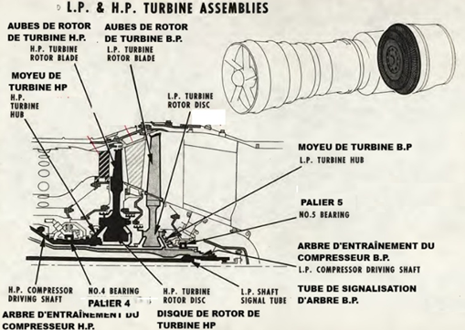
The single-stage HP and LP turbine assembly and the diffuser with the rear cone.
Turbine Assembly :
Turbines are exposed to the high-temperature, high-pressure, and high-energy gases emitted by the combustion chamber. They extract the power needed to drive the engine's compressors and auxiliary equipment via interconnecting shafts.
The turbine thus completes the engine's main rotating components. There are two independent turbine groups :
- The HP compressor.
- The LP compressor.
The first turbine exposed to the combustion gases is the one that drives the HP compressor. It has a stator stage of 32 segments, each with two blades. Each blade has 21 cooling air outlet slots on its trailing edge. The HP stators are secured by sixteen retaining segments. The rotor of the single-stage HP turbine is attached to the HP compressor shaft. The turbine rotor has 87 fixed blades. Each blade has 18 cooling holes. The front labyrinth seal is attached to the turbine and rotates with it.
The HP turbine is followed by the LP turbine.
The stator of the second-stage turbine consists of 24 segments, each with two blades. Holes are drilled in the outer segments to facilitate horoscope visualization of the trailing edge of the HP turbine rotor blades.
Just beyond the stator is the LP turbine rotor. It has 70 blades, each air-cooled through eight holes. The turbine is attached to the LP compressor by a shaft passing through the hollow HP drive shaft. A compressible film roller bearing, bearing number 5, provides support for the rear hub.
Exhaust duct assembly.
Exhaust diffuser :
The residual energy of the gas flow exiting the turbines now constitutes the engine's net power. Until now, the cross-section of the gas flow was annular, meaning it had a hollow core. Expansion across the entire tubular section was necessary. This transition occurs in a passage called the exhaust diffuser. As its name suggests, it also triggers the expansion of the exhaust gases ejected into the atmosphere.
The exhaust diffuser is an assembly consisting of an outer casing and an inner cone, connected by 10 blades. These hollow blades allow the passage of pressurization and ventilation air, as well as oil supply and recovery lines.

Finally the BP shaft break detection device :
The Olympus engine is equipped with a special device: the LP shaft breakage detection system.
The shaft is long and undergoes significant torsional stress; its breakage would cause the LP turbine to overspeed and possibly burst.
To avoid this serious inconvenience, the breakage detection device causes the engine to shut down in the event of a breakage.
The system shown below includes a helical ramp mechanism that disengages when the compressor is no longer at the same speed as the LP turbine.
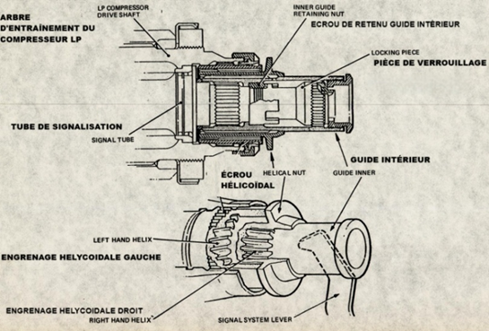
The disengagement causes a helical spline nut to move rearward.
The nut controls a lever that, via a cable, closes the "Quick-Shut-Down-Valve" fuel valve.
The compressor, turbines and their associated shafts are mounted on five bearings and constitute the main rotating assembly of the engine.
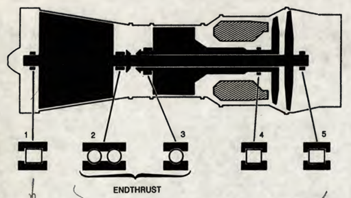
The LP bearing has a roller bearing in front of the compressor and a thrust (ball) bearing behind it, with a roller bearing supporting the end of the turbine, while the shorter HP bearing has a thrust bearing in front of the compressor and a roller in front of the turbine.
In short, this is “how it works” :
Viewed from the rear, the rotation direction of the assemblies is counterclockwise.
The turbine not only drive the engine compressors, but also provide the motive power ta drive the requi- site ancillary equipments. These equipments, including engine fuel and oil pumps among other accesories, are mounted on gearboxes.
The exhaust gases leaving the turbines may be reheated by the addition of fuel, via a fuel injection system, attached ta the bullet of the exhaust diffuser casing.
The engine includes a variable primary nozzle that contribute to maintain safely an optimum mass air flow through the engine.
The engine is contained within a ventilated and cooled area. Zone temperature and conditions ener- ally within the engine nacelle are monitored by a multiplicity of sensors, as are the engine healt parameters.
And after all that, if you want even more explanations from specialists, we advise you to refer to the SNECMA MUSEUM’s (previously Snecma) website.
In any case, today we can say a big thank you to BRISTOL and SNECMA for having initiated this marvel called « Olympus ».
All photos and documents from the AAMD collection (DR)..


What a compelling read! Your passion for the subject really shines through in your writing! by 世界盃
I appreciate the thorough explanations and diagrams. They make the content much easier to follow! by 3a娛樂城註冊
What a fascinating article! The technical details about the ATA 70-80 propellant unit are incredibly informative! by 紅襪 對 金鶯
Articles like this make you appreciate the complexity behind aviation. 姆巴佩
Articles like this make you appreciate the complexity behind aviation.