
POWERPLANT. ATA 70 – 80. Part 6
- 17 juil. 2025
- 7 min de lecture
After a long hiatus, here is the continuation of this important series of articles on 02’s powerplant.
Now let's continue with the rear part of the nacelle :
Concorde's engine is equipped with a converging-diverging nozzle assembly, consisting of the primary nozzle and the secondary nozzle.
This assembly directs and channels the exhaust gases to achieve optimal performance for each flight configuration.
The primary nozzle, thanks to its variable cross-section, has the primary role of regulating the N1 speed.
The secondary nozzle improves engine efficiency and also allows thrust reversal on the ground and in flight.
- The primary nozzle.
- The secondary nozzle.
- The thrust reverser.

Now we can talk about the nozzles :
How it works :
As we explained previously, in cruise condition, the expansion rate through the airflow is high and the expansion of the exhaust gases continues downstream of the primary nozzle.
One of the requirements of the nozzle will be to convert the potential energy contained in the airflow into actual forward thrust and transmit it to the aircraft.
Conversely, at low aircraft speed, the airflow expansion rate is low. This creates a ring of low pressure around the flow and therefore a base drag which is minimized by reducing the surface area of the nozzle.
During transonic accelerations, the surface area of the nozzles must be increased as a function of the Mach number in order to optimize the performance of the propulsion system.
The primary nozzle thus fulfills the function of a variable secondary nozzle, it is :
- convergent in take-off mode.
- divergent in supersonic mode and.
- in an intermediate position during transonic acceleration.
This increases the pressure in the annular space around the airflow and further reduces base drag. The apertures close gradually during transonic acceleration and are fully closed in supersonic mode. If reverse thrust is required, the airflow is directed forward reducing the nozzle neck area to zero, i.e. fully converging the nozzle by opening the apertures.
The engine is equipped with a set of converging-diverging nozzles, consisting of the primary nozzle and the secondary nozzle.
To establish the rotational speed of the LP compressor (N1) in reference to the rotational speed of the H.P. compressor (N2), the area of the primary nozzle must be checked.
The rotation speed of the LP compressor (N1) is a function of the expansion rate through the LP turbine. For this purpose, the expansion rate is determined by sensing the pressure ratio across the turbine B.P. The area of the primary nozzle is adjusted to maintain the reference relationship P 3 : P 7 and therefore the desired N1.
EJECTION OF GAS
The ejection assembly consists of two variable section nozzles (primary nozzle and secondary nozzle/eyelid thrust reverser) and a lobes silencer. The primary nozzle is operated by pneumatic cylinders, the secondary nozzle and the silencer lobes are operated by pneumatically controlled screw jacks.
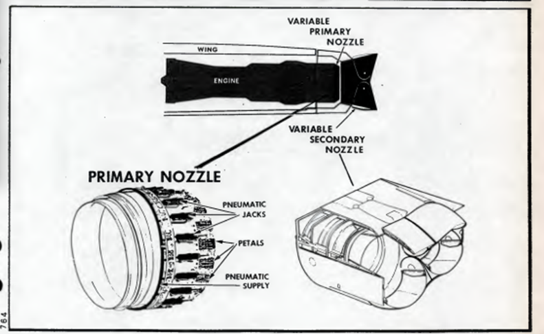

PRIMARY NOZZLE
The primary nozzle is automatically regulated so as to maintain the adequate N1/N2 ratio: The section of the nozzle depends on the position of the throttle lever and the E law. When using reheats, the section increases and maintains the pressure in the ejection channel and therefore the N1/N2 ratio at the correct values.
SECONDARY NOZZLE / EYE LID PUSH REVERSER
The secondary nozzle is made up of the thrust reverser lids which are operated by their actuators so as to obtain the optimal section ensuring maximum propulsive efficiency throughout the operating range. At low speeds, up to Mach 0.9, the eyelids are fix. At higher Mach speeds, the eyelids are automatically actuated based on the ratio of ambient/exhaust gas pressures.
In reverse thrust, the eyelids move rearward and are fully deployed to deflect exhaust gases through the opening created at their forward edges. A movement of the eyelids due to a system failure both in forward thrust and in reverse thrust causes an automatic reduction to engine idle speed. Within certain limits, the use of reverse thrust in flight is permitted; the power is limited, in these conditions, to reversing idle.
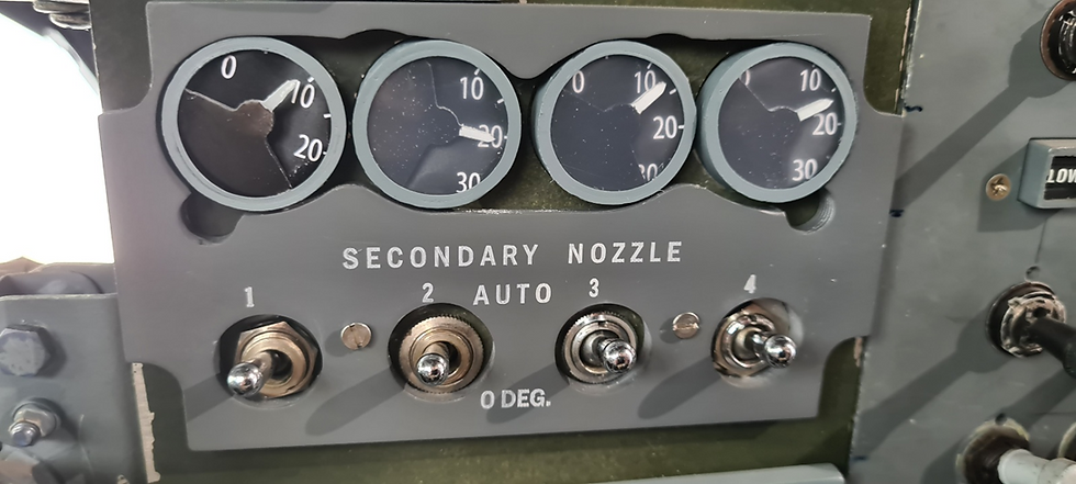
There are secondary nozzle controls and signals, which allow a choice of either auto or subsonic. The subsonic position is chosen for maximum reduction in takeoff noise (eyelid angle: 10 deg.).
This assembly makes it possible to direct and channel the exhaust gases in order to obtain optimum performance for each flight configuration.
EXHAUST SILENCER
Consists of a number of lobes, located in the conv./div. nozzle neck, protruding into the flow to attenuate takeoff noise.
PRIMARY NOZZLE
The basic arrangement for actuation and control of the primary nozzle is an extension of the ejection tube which precedes the secondary nozzle assembly.
The primary nozzle comprises a series of petals, actuated by air control cylinders, so as to modify the exit area of the converging nozzle as required.
The final position of the petals of the primary nozzle, and therefore the surface area of the primary nozzle, is a function of the relationship between the pressure of the nozzle and the pressure of the air in the control cylinders.

SECONDARY NOZZLE
To reduce drag, a complete overhaul of the secondary nozzles was undertaken. Those installed on the prototypes, made of a traditional and heavy construction, were replaced with lighter versions that no longer had a circular nozzle outlet like the engine, but a rounded shape. This modification achieved a significant weight saving.
The secondary nozzle improves the engine's efficiency and also allows thrust reversal on the ground and in flight.
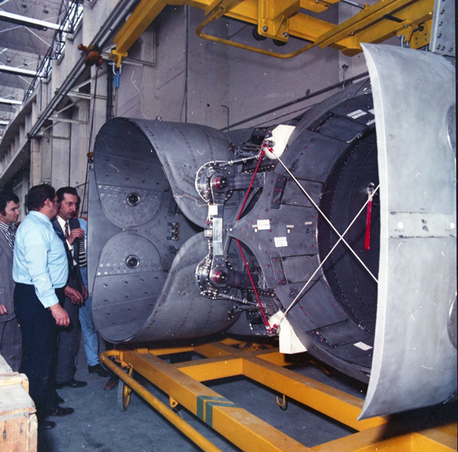
This nozzle aims to achieve the best gas expansion efficiency with the lowest possible drag and to provide thrust reversal.
At altitude, during cruise at M 2.02, the secondary nozzle channels the exhaust gases and thus prevents their unnecessary expansion into the atmosphere. This has the effect of increasing thrust.
The secondary nozzle is used in four main flight configurations :
- takeoff with a constant eyelid position of 21° up to M = 0.55.
- subsonic flight up to M = 1.1 with the eyelids automatically regulated from 21° to 0°.
- supersonic flight with the eyelids fully open at 0°.
- braking with the eyelids fully closed.

The main elements that make up the secondary nozzle are :
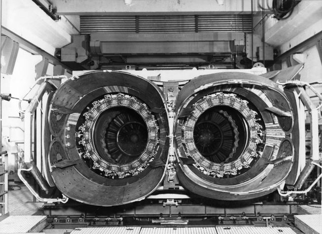
- the fixed base structure that encompasses the two engines.


- a pair of mobile eyelids from O to 73°.

- a mechanical eyelid control system.
- an electronic control and regulation system.
The eyelids are moved by a pneumatic mechanism housed within the structure.

The eyelids are controlled and monitored electronically.
The curve represents three distinct phases :
- up to M = 0.55, the eyelids are partially closed at 21°.
- from M = 0.55 to M = 1.0, the eyelids open slowly, then.
- from M = 1.0 to M = 1.1, the eyelids open more quickly until they are fully open (0°).
It is during this phase that the convergent-divergent flow begins, with the previous phases reducing drag; this is achieved by the penetration of tertiary air into the secondary nozzle, which acts as an aerodynamic air cushion.
THRUST REVERSERS
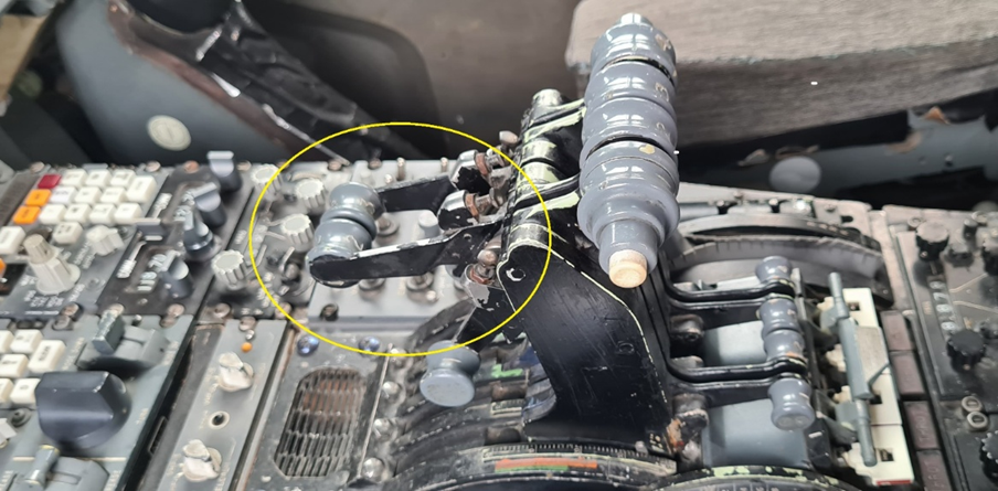
Manual control of the secondary nozzle for thrust reversing is achieved by a conventional thrust reverser lever, installed on the forward thrust lever.
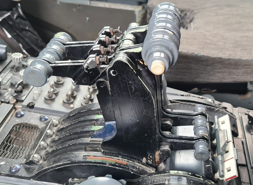
Each lever is equipped with an electromechanical locking device that prevents unwanted maneuvers such as :
- operating the reverse lever before the forward thrust lever is in idle position - displaying reverse power before the eyelids have reached the reverse position.
- displaying forward thrust while the eyelids have not returned to their normal position.
When reverse is selected, the primary nozzle will first open to facilitate the "transit" of the eyelids by reducing the jet speed.
Then, the primary nozzle will close to increase the jet speed and increase the effectiveness of the reverse.
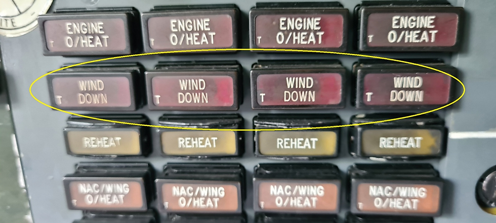
In addition, a separate safety device, called "WIND-DOWN," returns the engine to idle in the event the eyelids move from the open or closed position, when the throttle levers are not in the idle position.
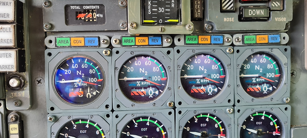
The secondary nozzle signaling includes an indicator located on the mechanical panel, and the "REV" and "CON" power indicator lights located on the pilot board.
The indicator needle indicates the eyelid position from 0 to 37°.
The blue "REV" light flashes when the eyelids move between 27° and the reverse position; when the eyelids are in the reverse position, the blue light is on and remains steady.

The "CON" light comes on if the eyelids are not positioned correctly according to the lever position.

Reverse can be activated in flight on both symmetrical engines 2 and 3.
In this case, the P3 air pressure required to move the eyelids is insufficient because the engine is idling at the time of reverse activation.
To overcome this drawback, air is drawn from the adjacent engine using a device comprising an interconnecting valve controlled by a "FLIGHT-REVERSE-ARM" pushbutton on the engineer's panel.

The opening of the valve is indicated by the blue "OPEN" indicator light located next to the inverter. The adjacent engine speed will be increased during the transit period of the lids both when they open and when they close.
Thrust control lights :
Green “AREA” light
ON : Indicates that the secondary nozzle buckets are located within limits, that the "CON" indicator light is off, that the index values pre-displayed on the P7 and FUEL FLOW indicators have been reached and, that for engine nb 4 the ENG 4 T/0 N1 LIMITER switch has returned to the NORMAL position.
The amber "CON" light
Illuminates if the eyelids are not positioned correctly in relation to the lever position.
Blue “REV” Light (Revers)
STEADY ON : Indicates that the buckets are closed.
FLASHING LIGHT : Indicates that the buckets are in transit.
OFF: Indicates buckets are in positive thrust range.
To conclude this series of articles on the propulsion system, we'll focus on the most important one: the "BRISTOL" engine, which will become the "ROLL ROYCE" engine and will be our next article.
To be continued...


Commentaires