POWERPLANT ATA 70 – 80. Part 5
- 23 oct. 2024
- 6 min de lecture
Before focusing on reactors, we will talk about the other essential parts of propulsion and this little reminder.
Concorde is equipped with four thrusters grouped in pairs in two nacelles under the wing, ROLLS-ROYCE/SNECMA type Olympus 593-610 reactors developing a gross thrust of 14,700 kg dry, and 17,400 with reheat.
This reactor is a classic subsonic engine; which needs the regulation of the air intake which we talked about in part 4 and which aims to ensure that the speed of the air arriving at the reactor does not exceed Mach 0.5. The aircraft's propulsion allows Concorde to reach Mach 2.02.
The main parts of the thruster consist of:
- The nacelle,
- The turbojet (which we will talk about later)
- Reheat.
- The primary nozzle.
- The secondary nozzle.
The nacelle:
The two parts that attract all eyes when passing the fuselage of the SA are the two nacelles.
Below we can see the difference in the rear part of the nacelle between the prototype and SA.
Prototype SA and serie
Each nacelle contains two reactors; it is divided into two structurally independent parts which contain:
- Air intakes.
- The engine compartments.
- The reheat.
- The backward extension which contains (which we will develop in our next article).
- The primary nozzle.
- The secondary nozzle and
- The thrust reverser.
The thrusters are grouped in two nacelles located under the wings on the right and left and each house two reactors.
The nacelle is divided into three sectors:
- The air inlet and the ducts bringing the air to propel,
- The reactor which ends with the heating part,
- Primary and secondary nozzles and thrust reversers.
Air intakes:
In the front part of the nacelle is the variable air intake that we talked about in our article previously.

Engine compartments:
The most important features regarding the construction of engine compartments result from the high operating temperatures and pressures inside the compartment and the necessary protection against possible fires.
- Maximum accessibility has been given to engine accessories and nozzles.
- The two compartments are limited by the central partition and the structure of the nozzle housing, as well as by the main access door.
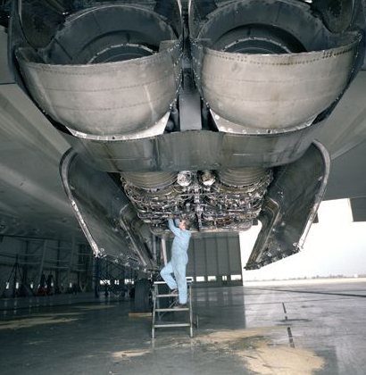
Two generously sized doors open partially or entirely, and allow access around the reactor. For maintenance operations, inspection doors are fitted; in particular, for oil fill-ups and tire park plugs.
The central part is equipped with two hatches which give access to the fasteners and the different elements of the reactor as well as their periodic change or troubleshooting.
Here we can see the accessibility to the two reactors by opening the two access doors under the lower part of the right and left nacelle.
- The front main doors are made of light alloy and their joints and fittings are made of titanium.
- The rear main doors are made of titanium.
- The central bulkhead is made of welded Inconel honeycomb: in addition to its structural functions, it serves as a firewall between the two engine compartments. The central bulkhead is divided into two panels of equal length to prevent it from limiting the bending of the sail in the direction of the chords.
- The rear nozzle structure carries the thrust reverser eyelids and the secondary nozzle. She is subjected to high temperatures and pressures; it is made of Nickel alloy and stainless honeycomb for the panels.
The engine compartment is suspended from the wing to reduce interactions with wing flexion.
The mounting of the engines is independent of that of the compartment and includes an articulated titanium wheelhouse mounted directly on the lower surface of the wing. It is designed to maintain alignment with the air inlet when flexing the wing. The light alloy wing lower surface is protected against heat in the engine compartment. This protection is made with silica wool, covered on the lower wing side by a resin glass envelope and on the engine side by a stainless steel sheet.
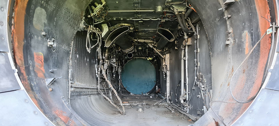
Now we will try to describe theoretically how it works knowing that on the SA our reactor nacelles are empty. que sur le SA nos nacelles réacteur sont vides.

We can see here in the photos the location of the thruster and the two cooling air outlets of the 2 heat exchangers (primary and secondary) for the air conditioning circuit. The air taken from the air intake passes through the secondary air flap. When the gears are extended (low speed), the circulation of cooling air is improved by the opening of a valve supplying the exchangers creating a depression at the outlet of the heat exchangers.

The reactor being absent but continuing our tour of the nacelle we arrive in the part where the reheat was located, which is also called the “afterburner”.
Reheat:
Since the basic engine design requirements have determined that a variable primary nozzle shall be fitted, a reheat system can be provided with very little weight penalty.
The purpose of the reheat system is to provide an additional thrust in order to achieve the required total thrust (dry engine thrust plus reheat thrust).
Reheat increases the thrust of the propulsion unit.
For each reactor, this increase is approximately:
- 18% at take-off and
- 14% in transonic acceleration,
Which provides with the four thrusters an additional thrust almost equivalent to a fifth reactor, this with a low penalty for aircraft weight.
The reheat is used:
- On take-off to reduce the taxiing distance
- In transonic acceleration between M = 0.9 and 1.7 to allow Concorde to quickly reach cruising altitude.
- On climb with a broken engine,
- On approach with two engines broken down.
How it works:
The reheat system is very simple in its technological definition.
It essentially includes an injection rail, a fuel regulator and an amplifier which controls and monitors the regulator.
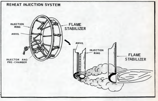
The injection system is fixed on the rear cone of the reactor, it includes:
- A deflector called an “anvil”
- A flame stabilizer and
- A pre-chamber in which a spark plug is fixed.

The injection rail forms a ring with orifices intended to inject the fuel countercurrently into the ejection channel. The fuel is projected onto the anvil, mixes with the exhaust gases and burns in the wake of the stabilizer.
Within the limits of the reheat system itself, the amount of fuel that can be burned in the nozzle depends on whether the engine is running dry.
Fuel is routed from the first stage fuel pump to a reheat fuel controller which measures the fuel entering a reheat injection system located in the reheat jet pipe.
Overall control is carried out by an Electronic Reheat Control Unit (R.E.C.U.) which includes control programs and limitation networks.
The reheat ends with the reheat channel which leads the air flow towards the nozzles which we will talk about in our next article.

The reheat system falls into three basic parts·:
- The fuel controller
- The reheat injection system
- The reheat electronic control unit.

The reheat can be switched on when the control inverter located below the power levers is on "REHEAT", and the N1 speed is greater than 81%.
The amplifier activates the ignition circuit which includes an HE transformer and the spark plug.
The amplifier controls the reheat to turn off in the following cases:
- N1 regime less than 70%
- Movement of the power levers, less than 10% of travel from idle.
In the event of an ignition fault, the amber “CON” light located on the central dashboard comes on.
Now what we can see in the cockpit:

Amber “CON” light:
ON: Indicates in the absence of N2 drop a loss of thrust reheats. On when thrust reversal is used, indicates that the position of the primary nozzle is greater than 15.
The heating is started on the central console just behind the throttle levers using four paddles.

Below are the 3 positions of the paddles:
In low position – reheat OFF.

In centre position – reheat SELECTED.
Amber light on AJ indicator indicates that the heater is selected.

In high position – reheat ON.
On take-off, the reheats activation sequence begins from the armed position by placing the central paddles 2 and 3 in the upper position which activate the reheats of the engines 2 and 3.
This is followed by the engagement of paddles 1 and 4 which activate the reheats of reactors 1 and 4 to achieve maximum thrust.


When the four paddles are activated, as shown in this photo, the equivalent of 360,000 HP begins to roar...
Imagine THE FRUSTRATION of the owner of a 2 CV Citroën...
Now an interesting discovery: the sides of the paddles are painted red to see if the paddles are aligned all together or in pairs when activated.

When we started this article, not being specialists, we had no idea of the magnitude that this represented in trying to explain it simply, "how it works" so you will have to be patient because there will still be a lot of things to do say.
To be continued…


Commentaires