
Between the cockpit and your seat, technical visit. Part 2.
- 26 nov. 2020
- 7 min de lecture
Equipment bays :
Let's be a little chauvinistic by saying that we can associate these equipment racks with the Norman cabinets of our grandmothers. Because they contain treasures ... the innovation, the mind, the heart and all the organs that allowed Concorde to become this exceptional aircraft.
We are not going to transcribe the maintenance manual here, we will simply try to show some equipment that was hidden in the Norman cabinet by positioning it in the shelves.
Equipment storage :
To accommodate all electrical and electronic equipment, the racks were located in the various flight compartments, in the front and rear vestibule and in the compartments under the floor.

The racks are designed to accommodate standard ATR (Airlift Shelving) size equipment, which are mounted on removable shelving modules on the shelves, connected at the back by connectors and secured at the front by assemblies of retaining screws or locking handles.

The shelves are positioned on slides and fixed to the shelving by bolts on each side. Each shelf is identified by a prefix number appended to the zone identification code. Electrical connections to the units are made via junction boxes at the rear which are an integral part of each shelf. Aircraft wiring connections are made through plugs and receptacles on the junction box.
The location of the equipment racks below was effective on planes: 01 and 02
Compartment 123 equipment identification zone - right side.

89 locations are marked in this compartment :
1. Overheat control unit (No, 4 nacelle)
2. Overheat control unit (No. 3 nacelle)
3. Fire detector control unit (No.4 engine)
4. Fire detector control unit (No.3 engine)
5. Turbine cooling amplifier (No.4 engine)
6. Turbine cooling amplifier (No.3 engine)
7. Master warning control unit (No1)
8. 26 V. 1800 Hz inverter No.2 (green)
9. Control and protection unit (No.4 generator)
10. Control and protection unit (No.3 generator)
11. Vertical speed indicator amplifier (flight test)
12. Vertical speed indicator amplifier
13. De-icing temperature controller (right hand)
14. Load controller (No 4 constant speed drive)
15. Load controller (No.3 constant speed drive)
16. Ice detector relay unit (right hand)
17. Instrument integral lighting control unit (S. P.)
18. Master air control unit (No.4 engine)
19. Master air control unit (No.3 engine)
20. Temperature regulator amplifier (group 4)
21 Temperature regulator amplifier (group 3)
22. Braking and anti-skid regulator (left hand and right hand outer)
23. Fuel level switching pack (left hand)
24. Fuel level switching pack (right hand)
25. Fuel quantity pack (total and centre of gravity)
26. Fuel quantity pack (load limit control)
27. Fuel quantity pack (trim tanks)
28. Fuel quantity pack (left hand tanks)
29. Fuel quantity pack (right hand tanks)
30. 26V. 1800 Hz protection unit (No.2)
31. Vertical vibration probe amplifier (No.4 engine)
32. Vertical vibration probe amplifier (No.3 engine)
33. Fire detection control unit emergency power unit
34. Audio warning unit
35. Low press, top speed governor control unit (No.4)
36. Low press, top speed governor control unit (No.3)
37. Nose droop asymmetric comparator unit (S.P.)
38. Fuel digital gauging error reducing system (S.P.)
39. Flame detector amplifier (No.4 engine)
40. Flame detector amplifier (No.3 engine)
41. Ground power protection unit
42 Windscreen wiper motor control unit (right hand)
43. Main battery charger (S. P.)
44. Domestic audio unit (S. P.)
45 Fuel heater control unit (No.4 engine)
46. Fuel heater control unit (No.3 engine)
47. Turbine blade temperature control unit (No. 3 engine-lane 1)
48. Turbine blade temperature control unit (No. 4 engine-lane 1)
49. Turbine blade temperature control unit (No. 3 engine-lane 2)
50. Turbine blade temperature control unit (No. 4 engine-lane 2)
51. Mach limit computer pack
52. Air conditioning over heat detection unit
53. Air conditioning over heat detection unit
54. No.4 bearing failure control unit (No. 3 engine)
55. No.4 bearing failure control unit (No. 4 engine)
56. Relay jack (logic unit)
57. Automatic flight control system central test assembly
58. Automatic pilot and flight director pitch computer (No.2)
59. Automatic pilot and flight director azimuth computer (No.2)
60. Automatic throttle computer (No.2)
61. Automatic flight control system electric trim computer (No.2)
62. Landing display computer (No.2)
63. Flight director No.1 and 2 switch unit (Co-pilot)
64. Take-off director computer (S.P.)
65. V.H.F. transmitter (No.2)
66. Air traffic control transponder (No.1)
67. Air traffic control transponder (No. 2)
68. D.M.E. interrogator unit (No 1)
69. D.M.E. interrogator unit (No.2)
70. H.F. trans. receiver (No.2)
71. Air data computer (No. 2)
72. Air data computer flight test (No. 2)
73. Vertical navigation computer (S. P.)
74. Artificial feel computer (No. 2)
75. Tape recorder unit (S.P.)
76. Public address amplifier
77. Interphone amplifier unit
78. V.H.F. No. 2 navigation receiver (V.O.R.)
79. Automatic pilot and flight director radio instrument switch unit (co-pilot)
80. V.O.R. No.3 (S.P.)
81. V.H.F. No.3 (S.P.)
82. Data link (S.P.)
83. Landing display radio aid (S.P.)
84. Accident recorder unit (S.P.)
85. Auto stabilization computer (No.2)
86. Control surface monitoring comparator
87. Control surface monitoring comparator
88. Control surface test unit
89. Elevons supply change - overlay unit
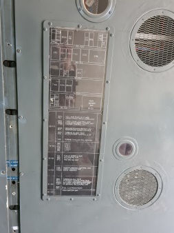
The front face of the equipment bay on the right side is closed by two screwed plates, one can see ventilation openings, access hatches to certain equipment (which avoided removing the entire front face) and two spotting panels for quick identification of the equipment behind the plates.


Above are still traces of equipment added during flight tests, the location of the public-address volume control (passenger announcement system), which was to be used during demonstration flights.

Currently in the right part of the equipment bay of the SA is installed all 28v and 5v power supplies dedicated to flight instruments and pilot station filament tests (Light Test), as well as the relays.

Photos taken before the final installation of the 28v and 5v cockpit power supplies was completed. Important note, all the new cables were installed without affecting the integrity of the aircraft, which required finding existing passages in the various partitions and floors.


Here we see the connection used to recover the function of pressing the Light test button of the Master Warning.


By severing the wiring in 1976, no one dared to think that one day certain functions would resume service on board the SA. Below is what we discovered under the covering of the ceiling towards the equipment bay area 123 left side.


By quickly helping us with the maintenance manual we will present the equipment bay that is missing on our aircraft :

76 locations are marked in this 123 compartment - left side :
1. Overheat control unit (No. 2 nacelle)
2. Overheat control unit (No. l nacelle)
3. Fire detector control unit (No. 2 engine)
4. Fire detector control unit (No. l engine)
5. Turbine cooling amplifier (No. 2 engine)
6. Turbine cooling amplifier (No. l engine)
7. 26 V. 1800 Hz inverter No. l (blue)
8. Control and protection unit (No. 2 generator)
9. Control and protection unit (No. l generator)
10. Vertical speed indicator amplifier
11. Wheel overheat indication amplifier
12. De-icing temperature controller (left hand)
13. Load controller (No, 2 constant speed drive)
14. Load controller (No. l constant speed drive)
15. Ice detector relay unit (left hand)
16. Electro luminescent dimmer unit (S.P.)
17. Electro luminescent dimmer unit (S.P.)
18. Electro luminescent dimmer unit (S.P.)
19. Electro luminescent dimmer unit (S.P.)
20. Landing gear fault detection unit
21. Master air control unit (No. 2 engine)
22. Master air control unit (No. 1 engine)
23. Cabin pressure control amplifier
24. Temperature regulator amplifier (group 2)
25. Temperature regulator amplifier (group 1)
26. Temperature control comparator
27. Braking and anti- skid regulator (left hand and right hand, inner)
28. Nose wheel steering control unit
29. 26V. 1800 Hz protection unit (No.1)
30. Vertical vibration probe amplifier (No. 2 engine)
31. Vertical vibration probe amplifier (No.1 engine)
32. Low press, top speed governor control unit (No.2)
33. Low press, top speed governor control unit (No.1)
34. Flame detector amplifier (No. 2 engine)
35. Flame detector amplifier (No.1 engine)
36. Windscreen wiper motor control unit (left hand)
37. Main battery charger (S.P.)
38. Emergency generation engine speed unit
39. Fuel heater control unit (No.2 engine)
40. Fuel heater control unit (No.1 engine)
41. Turbine blade temperature control unit (No. 2 engine lane 1)
42. Turbine blade temperature control unit (No.1 engine lane 1)
43. Turbine blade temperature control unit (No.2 engine lane 2)
44. Turbine blade temperature control unit (No.1 engine lane 2)
45. Emergency power unit inverter
46. Air conditioning overheat detection unit
47. Air conditioning overheat detection unit
48. No.4 bearing failure control unit (No.2 engine)
49. No.4 bearing failure control unit (No.1 engine)
50. Automatic flight control system central test assembly
51. H.F. trans receiver No.1
52. SELCAL decoder unit**.
53. H.F. transmitter - receiver (No.1)
54.V.H.F. No.1 navigation receiver. (V.O.R.)
55. Automatic pilot and flight director radio instrument switch unit (pilot)
56. Marker unit receiver
57. Automatic pilot and flight director pitch computer (No1)
58. Automatic pilot and flight director azimuth computer (No.1)
59. Automatic throttle computer (No.1)
60. Automatic flight control system electric trim computer (No.1)
61. Landing display computer (No.1)
62. Flight director No.1 and 2 switch unit (pilot)
63. Take-off director computer (S. P.)
64. Data link (S. P.)
65. C.T.F. / Aids (S. P.)
66. Automatic flight control system gain adjust unit
67. Artificial feel computer (No. l)
68. Vertical navigation computer (S. P.)
69. Air data computer flight test (No.1)
70. Air data computer (No.1)
71. Proximity warning (S. P.)
72. C.A.T. (S. P.)
73. Auto stabilization computer (No.1)
74. Ground position computer (S. P.)
75. T.V. (S.P.)
76. Light test navigation system (S.P.)*
Writer's note :
(S.P.) Indicates rack space that has only been provisionally allocated or is flight test instrumentation equipment, this indication can also be attributed to certain unused positions.
VHF (Abbreviation for English Very High Frequencies) Radio transceiver used for long distance communications.
SELAC, selective call for HF radio transmissions. Each aircraft equipped with HF radio receives a code (usually a combination of 4 letters), the base station on the ground can enter into direct contact with this code with the aircraft. The SELCAL emits a light and sound signal to signal the crew to establish the link radio.

The AJDM code is listed on the dashboard under the SA registration.
MARKER VHF radio beacon allowing the pilot to determine how far away is the start of the runway.
VOR (abbreviation of VHF Omnidirectional Range) is a radio positioning system operating with VHF frequencies.
DME (abbreviation of distance measuring equipment) distance measuring device is a radio-transponder which allows knowing the distance which separates an aircraft from a ground station.
TRIM (English word) is a compensator or an aerodynamic or mechanical system which makes it possible to maintain a control surface in a position allowing the balance of the airplane.
Our next article will end this short visit to the SA.
To be continued…


Commentaires