
AFCS or CADV.
- 23 févr. 2021
- 7 min de lecture
The first piece of equipment that looks on when entering the SA cockpit, in the centre just below the windshield, is the AFCS control box or CADV in French.

Let's go back a bit :

Cockpit photo taken on June 8, 1988 when the SA arrived in Athis Mons, we can see the AFCS print which was installed by Air France in 1976.Photo du poste de pilotage réalisée le 8 Juin 1988 lors de l’arrivée du SA à Athis-Mons sur son emplacement actuel. On peut y apercevoir l’AFCS qui a été installé par Air France en 1976.

This photo of our friend who died too soon Jean Claude DRAPS shows the cockpit shortly before the installation of Maxime's model.

Above the replica which was made by Maxime in 2012 :
According to the complexity of this system, just a few generalities on all the functions provided by AFCS.
The Concorde automatic flight installation AFCS (automatic flight control system) is designed to ease the pilot's task and ensure full piloting of the aircraft up to the landing wit :
- The auto-pilot (AP) and flight director (FD)
- Auto-Stabilization
- Electric Trim (on the pitch axis only)
- Auto-Throttle
- Landing Display
To simplify the explanations, AFCS acts on all the systems below :
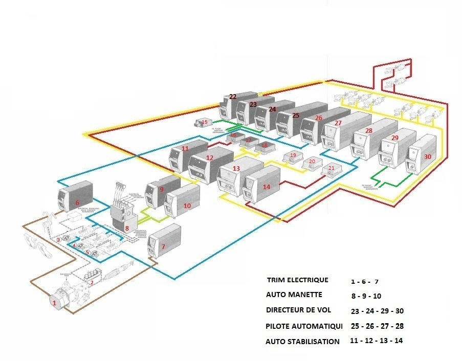
At the end of this article is the complete list of the equipment numbered above and the same diagram with the modifications which have been carried out on the production planes.
All the systems are fully duplicated and self-monitoring. Priority is given to No. 1 system and, in the event of failure; changeover to No.2 system is automatic.
- Data sources providing the various parameters required for flight
control.
- Data processing systems and control monitoring systems.
- Pilot’s and co-pilot indicators.
COMMAND BOX

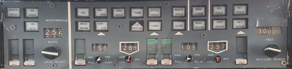
This box groups together all the AFCS controls in the form of pushbuttons which will be used to activate the various functions which are :
- The Autopilot AP
- The Flight Director FD
- The Auto-Stabilization system
- The Trim. Electric
- The auto controller
- The alarms and landing situation indicator
Various data sources provide the AFCS with the main data used as reference for aircraft automatic control. These data are supplied by systems, sensors and indicators, which are :
- Three Inertial Navigation Systems (INS).
- Two Air Data Systems (ADS).
- Two VOR radio receivers.
- Two ILS radio receivers.
- Two radio altimeters.
- Two Compass Couplers
- Eight rate-gyros (four for pitch axis and two on each of the two remaining axes (roll and yaw).
- Two lateral accelerometers.
- Two longitudinal accelerometers
- Three relay jack sensors (RJS).
- Two track and heading preselection units (THU)
- Two course deviation indicators (CDI) (course setting) integrated in the AFCS control.
AUTOMATIC PILOT - FLIGHT DIRECTOR
Concorde is equipped with two sets of Autopilot and Flight Director. The Autopilot and the Flight Director are integrated in the same computers and the modes of use of these systems are common.
This PA / FD set have been designed with the classic Autopilot modes. These modes make it possible to ensure control of the airplane throughout the flight envelope from the start of the climb until landing. All computation chaines are self-monitored.

SELF-STABILIZATION SYSTEM
The purpose of the artificial stabilization system is to improve the flight qualities of the airplane throughout the flight envelope. Artificial stabilization is opposed to various atmospheric disturbances and limits the consequences of the swerve following the shutdown of a reactor. It also enables automatic turn coordination for a Mach below 0.65.

System description:
This set includes :
- 2 engagement boxes
- 2 calculators
- 6 gyro meters (2 per axis)
- 2 lateral accelerometers
- 1 alarm system.
Each computer includes the calculation and monitoring chains for the 3 axes: Yaw, Roll and Pitch. Each computer is associated with three gyrometers, an accelerometer and a control box which allows each axis to be engaged separately.
Each stabilization system is linked to the Autopilot, to the airspeed control unit, to the anti-high incidence device, to the emergency piloting and to the associated landing situation system.
AUTO STABILITY
The compensation trim has the effect of improving the stability of the aircraft as a function of Mach, angle of attack, speed and Vc-VMo.
- Vc: Calibrated Air Speed (CAS)
- VMo: Velocity maximum operating
Stability correctors
-Mach function
In the transonic domain, the deflection variation law governs as a function of the Mach has an inverted slope, hence a specific static instability of the airplane. The Mach trim law has the effect of restoring a normal direction of variation of the force on the elevator control. Mach decrease Pull-up effort Mach increase: Punch down force this law is delivered by two potentiometers of the anemometric unit and provides a nose-up command when the Mach increases.
-Bearing function
The purpose of this function is to restore a correct force law to the handle for high incidences. This law is delivered by two potentiometers of the anemometric unit and provides a nose down command when the angle of attack increases.
-Speed function
This law is intended to increase the static stability of the airplane and to regularize the evolution of the longitudinal balance. Its role and the variation of the forces are identical to the Mach trim function. The speed trim law is delivered by potentiometers of the anemometric control unit.
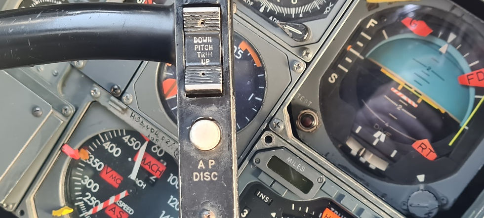
ELECTRIC TRIM
The three flight control axes (Elevator, Roll and Direction) are equipped with a mechanical trim, and only the elevator axis has, in addition, an electric trim. This electric trim can be controlled :
- Directly by the Pilot
- Independently of the Pilot in manual piloting. on autopilot.
The electric trim acts directly on the mechanical trim which moves the reference of the artificial sensation. Whether the trim is controlled by manual piloting or by automatic piloting, it is slaved to variations in Mach, incidence, speed (Ve), and the Vc-VMo deviation. In normal operation: both trims are engaged, trim n ° 1 has priority and operational, trim n ° 2 is on standby and in synchronization. The progress of the trim is indicated by the rotation of the steering wheel and by the operation of a bell.
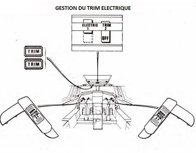
Position sur le manche coté
Pilote Copilote
AUTOTHROTTLE
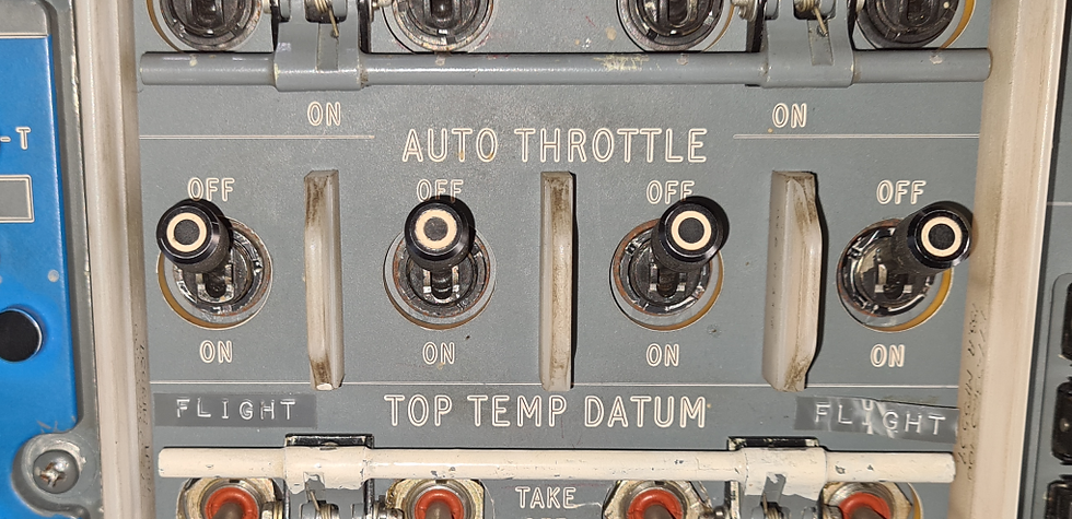


The Autothrottle system is a piloting aid in phases of flight requiring precise speed control. These phases can occur in subsonic and supersonic cruise during certain phases of ascent or descent, but more particularly in approach until landing.
The Auto throttle acts by moving the throttles and the electric control synchros of the reactors
Description and operation :
The manual control of the engines (throttle) can be operated by an automatic device known as auto throttle.
This device is an aid to the pilot in those phases of the flight when precise control of speed is required.
Instances are while cruising at subsonic or supersonic speeds during certain stages of the ascent or the descent but particularly when making an approach for landing.
It is not expected to use the auto throttle over the transonic range.
The auto-throttle system is independent of the auto-pilot although the control unit and the datum adjust unit regroups the controls of both systems.
The auto-throttle normally operates with four engines, but also with one engine failed.
There are three operating modes :
IAS HOLD Mode
This is the basic mode of the system. On engaging the system, this mode is engaged automatically. The auto-throttle holds the speed existing at the moment of engaging this mode.
MACH HOLD Mode
To engage the MACH HOLD mode, just press the MACH HOLD push-button on the auto-throttle control unit.
IAS ACQ mode
To engage the IAS ACQ mode, just press the IAS ACQ push-button on the auto-throttle control unit. The push-button illuminates indicating that the mode is engaged.
This operation has the effect of cancelling the mode previously selected. In this mode, the throttle movement orders throttle from the SPEED SELECT selector on the auto-throttle control unit.
This mode is used more for the approach. During the round-out phase, on flight director or auto-pilot landing, the auto-throttle partially closes the throttle below a pre-determined altitude if the IAS ACQ mode has been selected.
ALARM AND LANDING SITUATION INDICATOR
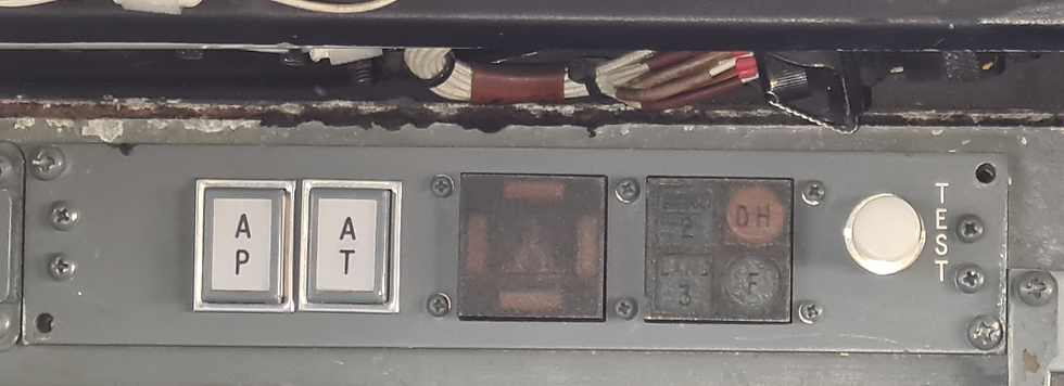

This system, mainly designed to help the pilot in the approach and automatic landing phases, also provides information on the state of integrity and the availability of peripheral systems. It provides information on the deviations of the aircraft's trajectory from the ILS references and displays the AP and Auto throttle failures.
This set includes two identical systems (Pilot and Co-Pilot).
Description and operation :
This installation designed for the approach and landing phase, informs the pilots on the state of integrity of the AFCS systems and on the aircraft's trajectory errors in relation to the ILS references.
Each installation is duplicated and each pilot is independently informed by his own landing display indicator.
Two flashing TAKE OVER captions situated on the sides of the AFCS unit complete the landing display installation assembly.
Diagram of equipment used by AFCS on production aircraft.

Diagram of equipment used by AFCS on pre production aircraft.
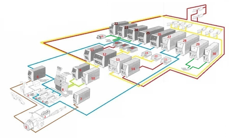
1 - Electric trim actuator
2 - Feel sensor assembly
3 - Relais Jack sensor-pitch
4 - Relais Jack sensor-roll
5 - Relais Jack sensor-yaw
6 - Electric trim computer 2
7 - Electric trim computer 1
8 - Autothrottle actuator
9 - Autothrottle computer 2
10 - Autothrottle computer 1
11 - Autostabiliser computer - yaw 2
12 - Autostabiliser computer - pitch & roll 2
13 - Autostabiliser computer - pitch & roll 1
14 - Autostabiliser computer- yaw 1
15 - Longitudinal accelerometer
16 - Rate gyroscope – yaw 2
17 - Rate gyroscope – pitch 2
18 - Rate gyroscope – roll 2
19 - Rate gyroscope – roll 1
20 - Rate gyroscope – pitch 1
21 - Rate gyroscope – yaw 1
22 - Take-off & over shoot director computer
23 - Flight director lateral computer 2
24 - Flight director longitudinal computer 2
25 – Autopilot computer lateral 2
25 – Autopilot computer longitudinal 2
27 – Autopilot computer longitudinal 1
28 - Autopilot computer lateral 1
29 - Flight director longitudinal computer 1
30 - Flight director lateral computer 1
And this little message is for Joseph and for Milo :
“On your next visit to the museum, we will organize a practical interview in SA’s cockpit.”…


Commentaires