
ATA 70 – 80 POWERPLANT. Part 4
- 8 juil. 2024
- 5 min de lecture
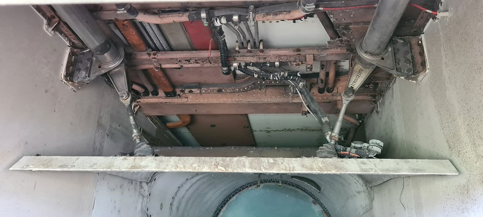
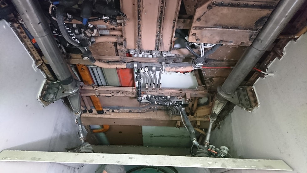
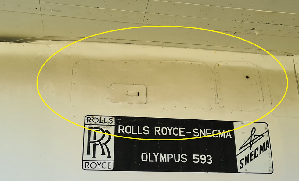
Now we will focus on the accessible and visible parts of the air intake on the SA.
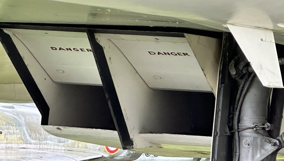
In the upper part of the air intake there are the ramps composed of two hinged sections mechanically connected and in the lower part the discharge doors.
The role of the air intake is to ensure satisfactory supply to the engine in all flight domains.
The flow velocity at the compressor intake must not exceed Mach 0.5. This slowing down of the air flow passing from a supersonic speed to a subsonic speed must be obtained without prohibitive reduction in the efficiency of the intake. The principle retained is that of the splitting of the shock waves which leads to a progressive braking of the flow.
To carry out this task, a control system was designed which varies the geometry of the air intake according to parameters measured locally at each air intake, and according to information provided from the anemometric circuits. The main variation of the air intake geometry is carried out by means of the two variable ramps. An auxiliary flap, freely articulated but provided with a damping device, is incorporated in the discharge door and operates thanks to the aerodynamic pressure created by the suction of the compressor, so as to provide an auxiliary air intake to the low subsonic speeds.
In our previous article we talked about the control system which was analog on SA, and which will subsequently evolve into digital on all production Concorde.
The majority of mechanisms: pumps, flap motors and spill door jacks were dismantled in 1976 when the plane arrived at Orly. Plywood lacquers were installed at the engines level and at the secondary « buckets » level.
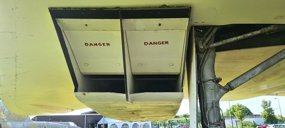
Today we are showing our visitors the flaps and air intakes on the right nacelle in the “low” position for supersonic flight and on the left nacelle in the “high” position for subsonic flight.
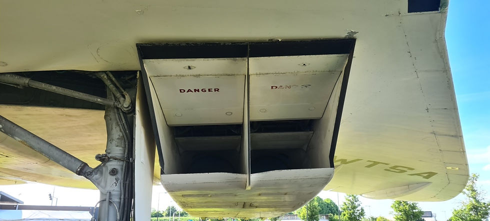
The spill doors and auxiliary flaps are in the closed position due to the absence of the actuations jacks dismantled in 1976. We are studying the possibility of put back in working condition at least one spill door.

Ramps
The front and rear ramps are hinged at their front and rear edges respectively and fluid-resistant terylene rubber seal strips along the sides and at the ends of the hinges reduce differential pressure loss across them.

The ramps are not interchangeable.
The front ramp has a crowned area to provide space between the ramp and the actuator when the ramp is in the up position.
The rear ramp has an anti-ice element on its front edge and two panels attached with quick clips providing access to the junction boxes. Connecting fittings are incorporated into the structure of the two ramps for attaching two connecting arms.
Front ramp

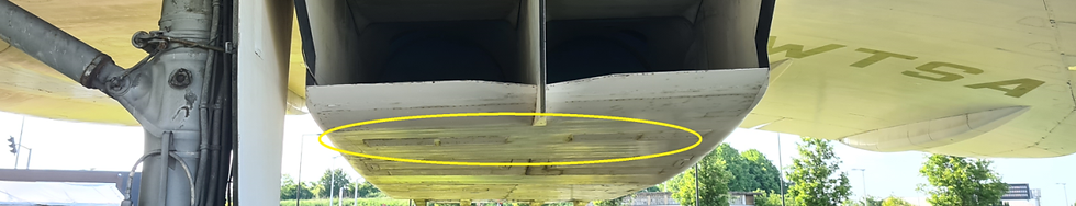
The low distance did not allow us to take a full photo of the front and rear ramps.
The rear ramps
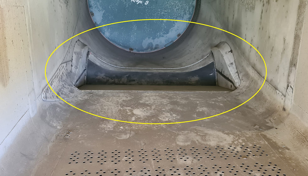
Rear ramp engine 1

Two new discoveries:
-This « BAS » marking indicating the low position of the rear ramp.


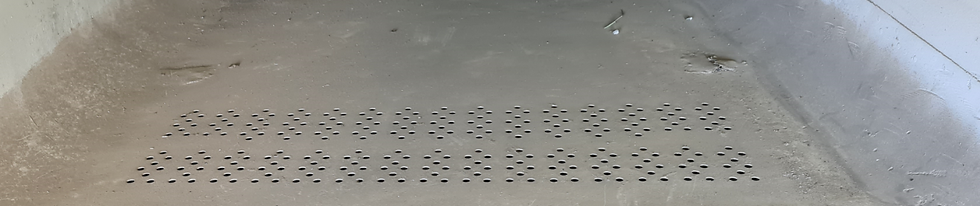
- And in the floor of each air intake this part which has several rows of holes and from which the air comes out below the lower engine cover.
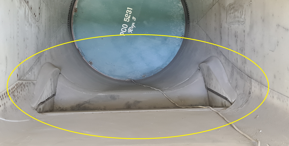
Rear ramp engine 2
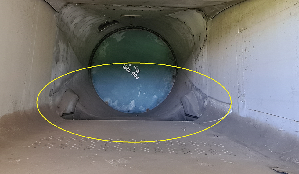
Rear ramp engine 3
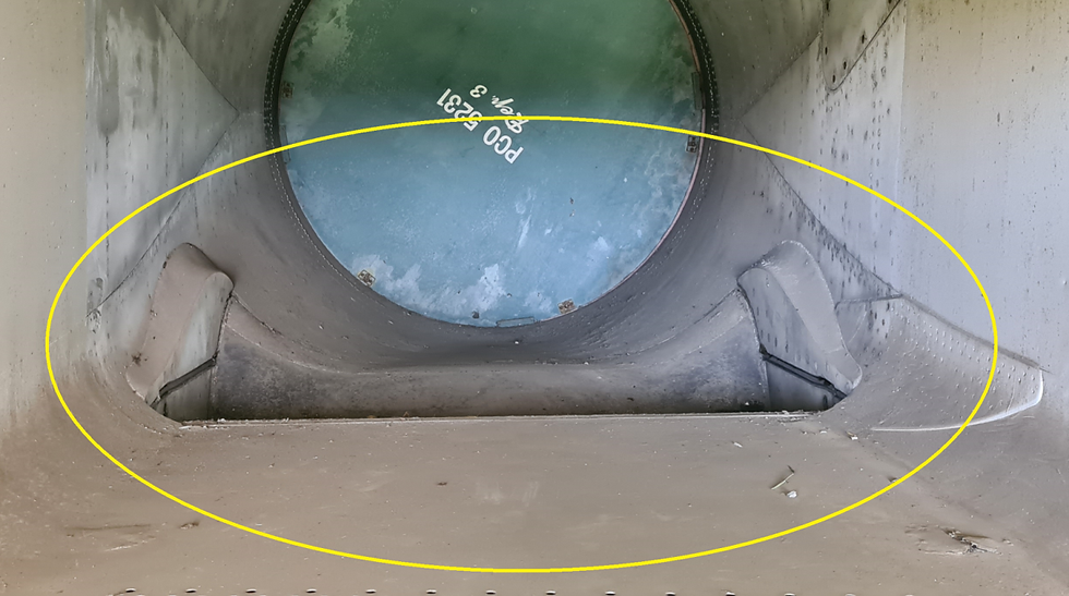
Rear ramp engine 4
How it works:
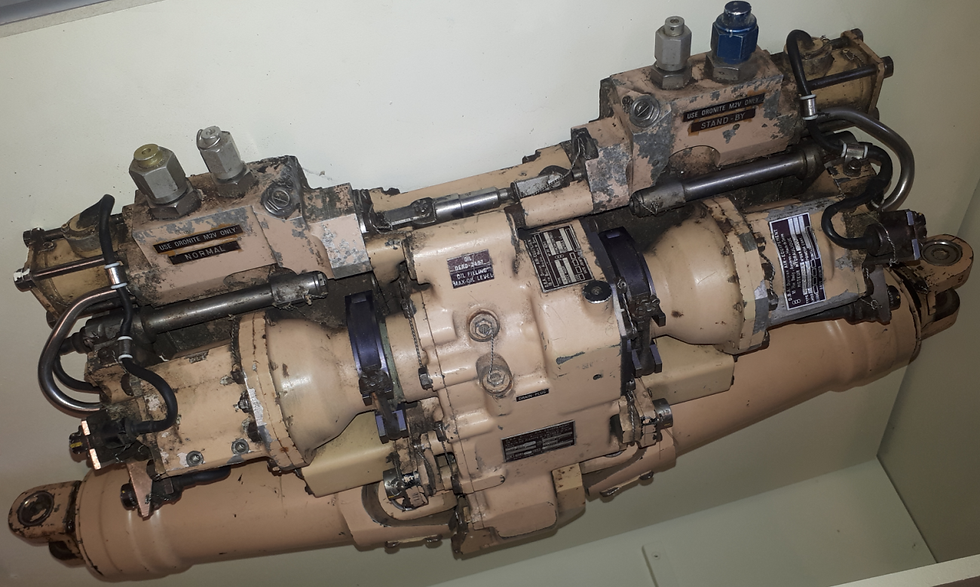
The actuator or Air intake ramp jack.
Two screw jacks are driven by a main reduction gear or emergency groups of hydraulic components to raise and lower the ramps.
Hydraulic motors fit into the reducer and are secured by quick release manacle clamps. Also attached to the gearbox housing are two hydraulic units, emergency and main, each carrying a solenoid selector and servo valve. The emergency hydraulic unit is also equipped with a braking test solenoid valve which activates a mechanical brake disc. Two position transmitters are also mounted on the gearbox and an end-of-stroke damping unit. The gearbox housing contains an oil bath with filling and draining plugs. Oil seals prevent fluid leaks between the motor and the gearbox housing. A hole in one end of the gearbox housing and an adjustable linkage on the other form the mounting points for the actuator assembly.

The reducer transmits drive to the two in-line screw jacks driven by the final stage of the reducer which extends to lower the ramps. At their inner ends, the screw jacks are fixed to the gear reduction by cardan couplings and at their outer ends by pins to levers secured to the torque tubes.


Photos of the actuator with the screw jack in the retracted position, and in maximum extension.

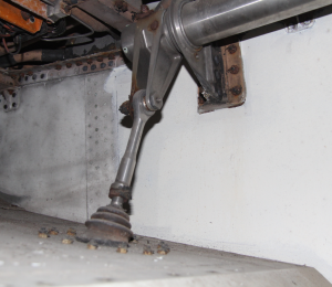
Mechanical connection
The mechanical link connects the actuator to the front and rear ramps. Two of the longitudinal torque tubes, one on each side of the actuator, are mounted in bearings attached to the intake walls.
Integrated levers attach a torque tube to the screw jack in the centre and the link arms at each end. The torque tubes convert the front and rear ramps into a single mechanism since each torque tube serves both ramps.


A position indicator lever is bolted perpendicular to the forward end of the left torque tube in each air intake. The lever indicates torque shaft position to an adjacent transmitter which has an adjustable body.


Two link arms connect each ramp to the torque tubes. The link arms are tubular with fixed and adjustable eye ends having spherical bearings. The adjustable ends of the link arms are each pinned and keyed to a link housing passing through the boom structure link fitting and locked by a special nut surrounded by a rubber cover.
The link arms
Rear In subsonic position Front In supersonic position


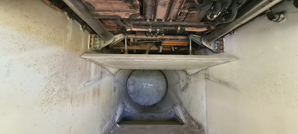
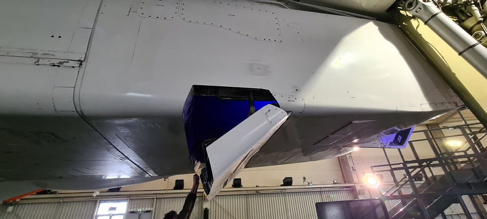
Spill door and the auxiliary flap.
A spill door is installed in each air intake to help regulate airflow to the engines, located at the rear of the intake.
The assembly consists of a door driven by a screw jack and a linkage.

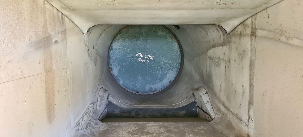
In the floor of the circular part are mounted the discharge doors made up of 2 independent parts used according to the flight phases.
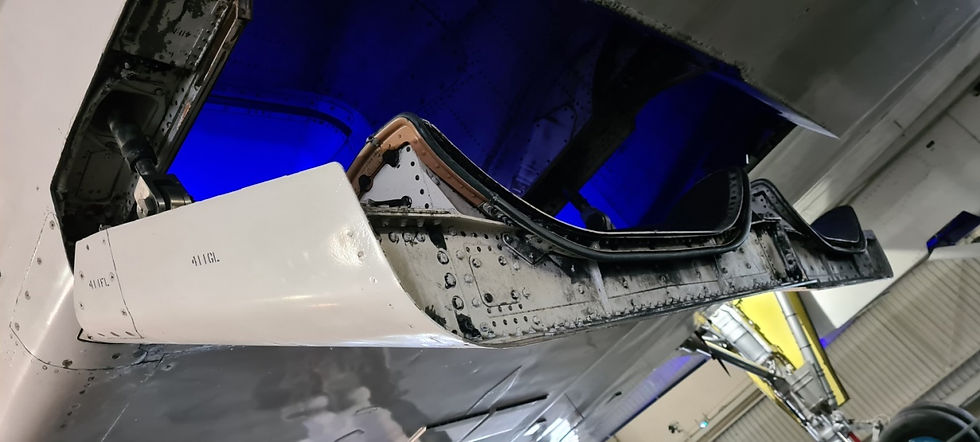
- Either as an auxiliary air inlet

Additional air entry is provided by an articulated flap in the door and opens inwards under the effect of the differential pressure between the inside and outside of the intake and creates a negative pressure in the air intake.
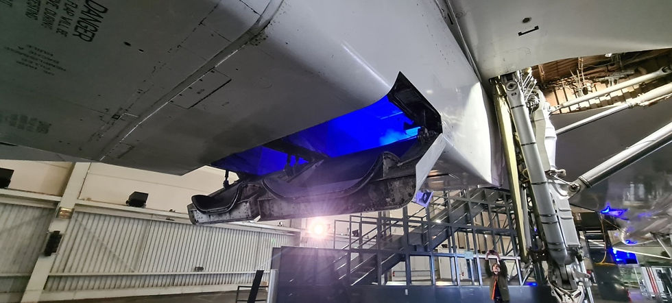
- Either spill from the air intake

When spilling air, the door hinged on its front edge opens outwards.
And what we can show you on the SA and the photos we received from our friends from Toulouse that we are studying to see if adapting a modern screw jack could be installed in the place of the missing one in the SA to show the operation to our visitors.
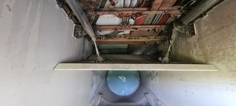
Spill door engine 1


Spill door engine 2
Spill door engine 3
Spill door engine 4
The actuator is supplied with high pressure fluid from the electro-hydraulically controlled intake hydraulic system. The door position is reported to the ICS by the position transmitters located under the actuator and operated by the linkage.


Access to the screw jack is located on the sides of the exterior covering of the nacelles.
To have a better view of the spill doors, a visit to the F-BTSD is necessary at the Le Bourget Air Museum, of which here are some views.
To be continued…
Editor's note: Initially the following article was to be devoted to the turbojet, but given the scope of the subject we will leave it for after the Olympic Games PARIS 2024.


Commentaires