Between the cockpit and your seat, technical visit. Part 3.
- 3 déc. 2020
- 4 min de lecture
We do not pretend here to say everything about the electric generation of Concorde, but just want to show the two types of electric currents that can be encountered there and that operate the electrical equipment of the aircraft, which are:
Alternating current (AC) *
* Alternating current (AC or AC for alternating current) is an electric current in which electrons circulate alternately in both directions of the circuit. It is obtained by the rotation of an alternator or a generator which can be single-phase or three-phase and generated in our case by an alternator driven by the jet engine.
Direct current (DC) **
** Direct current (DC or DC for direct current) is an electric current in which electrons flow continuously in the same direction, from the negative pole to the positive pole.
On the SA. All the electrical equipment was dismantled in 1976 when it arrived at Orly, and in view of the remaining potential and after an overhaul; they certainly had to be reused on subsequent planes. Here we only present the locations and their description in the maintenance manual. Fortunately, however, most of the wiring has not been cut, it is in place in the equipment bay on the right side and some are even reused in the return to service of certain circuits.
Electric Generation
Electrical power for the aircraft is obtained from engine-driven ac generators which supply power to the AC distribution system and installations after transformation, but also by the means of supplying the aircraft from ground source.

Main power supply
The main 200/115 V three-phase 400 Hz AC power supply is generated by four 60 kVA generators which are mounted one on each main motor and driven through associated constant speed drive units (CSD s).

Each generator supplies the main bus bars with AC via the generator circuit breakers (GCBs). The main bus bars can be interconnected by link circuit breakers (BTB) and split circuit breakers (SSB) so that the generators can operate the four main bars in parallel or in any combination, including operation of one single generator.
DC Power
Four rectifier transformers (TRUs) are supplied with three-phase alternating current and provide 28 V DC power. TRU’s are supplied by alternating current.

We must also talk about two possibilities for supplying some or all of the equipment when the engines are stopped.
External Power
Provisions made for connection of a 200 / 115 V three - phase 400 Hz AC supply to the aircraft from a ground source. This supply is distributed to certain services via a ground power bus bar but can be further connected to the AC distribution system through a ground power breaker (GPB) and, ether fore, will also supply the DC distribution system via the TRU s.
Batteries
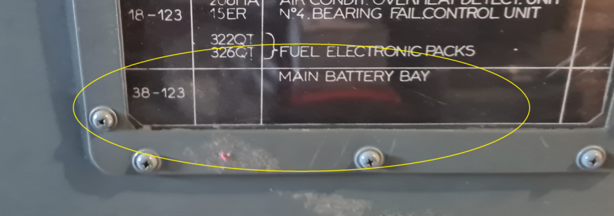
The two batteries, together with their associated am meter shunts, are located in the left and right-hand racking (panels 37 - 123 and 38 - 123 respectively). Each battery is a 24 - volts. Electrical connections are made at a two - pole receptacle with a quick - release plug.
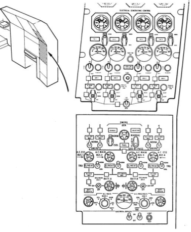
There is also the location of the circuit breakers that are an integral part of the aircraft's electrical system and that occupied the top of the equipment racks.
Below is the circuit breaker panel which remained in place in 1976 on the right hand side and is still actively used for certain functions of the pilot station and the lighting of the SA.

Small reminder before dismantling the same circuit breaker panel was facing the left side.

Now we can say quite simply, that the handling of all this was only possible in our SA and the other Concorde thanks to the mastery of the flight engineer, who worked on his electrical panel and who supplied power through the main bars, essential, and omnibus (we will pass the best bars in the stopovers) all the electrical equipment necessary for the proper functioning of the plane.
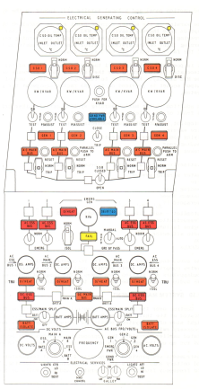
Some images of the electrical control panels of the SA flight engineer.

Below the hydraulic and electrical panel is still being rebuilt but we are still missing some elements to be able to reconnect the electrical supplies and finish the advertisers whose manufacture has been seriously slow down by COVID. But we hope to be able to show it to you again in place soon.
To finish what we can now show concerning the battery compartment of the SA.
The two 24 volt batteries, with their associated aerometric shunts, are placed in the left and right racks of the flight compartment (panels 37-123 and 38-123 respectively). Electrical connections are made on a bipolar price with a quick release plug.

A plastic tray, mounted on the cell drawer container, forms the lower part of the ventilation chamber, a combined cover and retaining frame fit the plastic tray and the top of the ventilation chamber. An air inlet plug and a non-return valve are installed at the end of the chamber; at the other end, to a threaded outlet nozzle, is mounted in a well in the tray to be coupled to an exhaust air pipe. The gases generated by the battery are released through vent plugs in the ventilation chamber.
During flight, the cabin is pressurized; air enters the cap, passes through the ventilation chamber and, evacuates the gases into the atmosphere. On the ground, when the cabin is not under pressure, the non-return valve requests the gases to escape through the inlet plug.


Here we really savour the pleasure of being able to share with you, all the markings, references and part numbers, and especially these small inscriptions left by the companions at the factory during manufacture, which we regularly discover in the hidden parts of the SA.


Now you can reach your seat in peace, we wish you a "pleasant flight" and see you soon in the SA for new discoveries.


Commentaires