ICOVOL
- 4 mars 2022
- 2 min de lecture
Still visiting the cockpit, one can see on the central panel of the dashboard an important indicator, the ICOVOL (Flight Control Indicator) which visually informs the crew of the position of the control surfaces.
It is important to differentiate between the flight controls on a:
Conventional aircraft A and
Delta wing aircraft B
- A is equipped with flaps, ailerons and rudder.
- B a supersonic airplane is equipped with: elevens* and rudder.

* An elevons is the control surface placed on each trailing edge of a delta wing combining the action of pitch control (elevator) with that of roll (aileron).

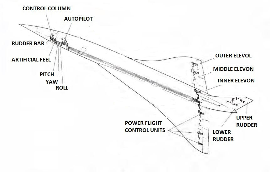
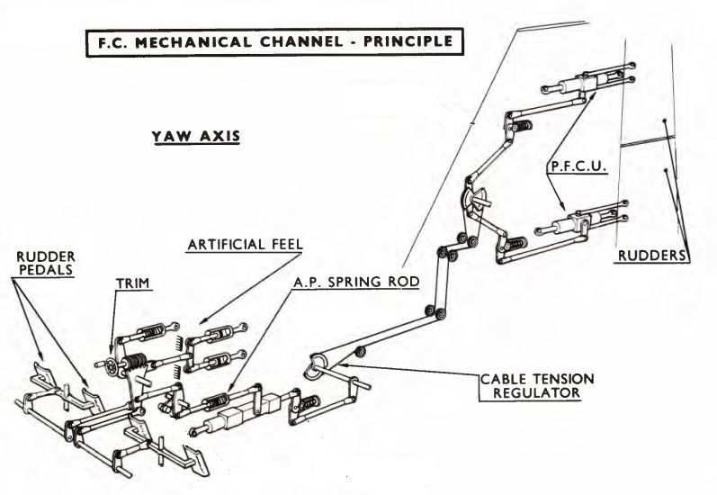
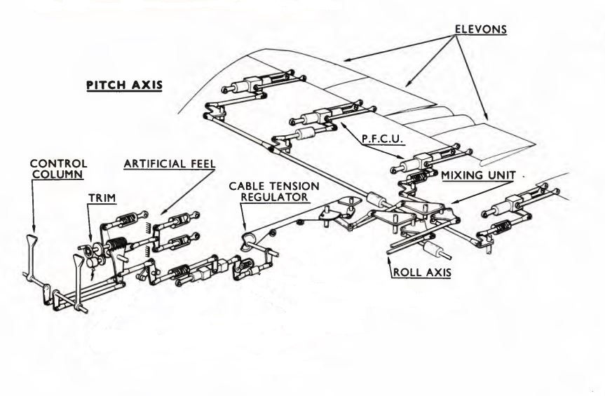
Below is the representation of the mechanical chains of the flight controls which are used in the event of failure of the electrical controls. The aircraft is much less comfortable to fly in this mode. These mechanical controls only control the hydraulic servos like the electrical controls do:


The ICOVOL is located on the central panel of the front dashboard where it informs the crew at all times of the status and position of the flight controls:
- Elevons and
- The rudders.


It shows for each control surface:
- the position indication, a mobile index which moves in front of a scale controlled by a special sensor installed on each servo-control
- Indication of the operating mode above each scale, which appears on a magnetic light (B on BLUE background, G on GREEN background, M on RED background).
B (BLUE),
G (GREEN),
M (MECH.)
These lights are controlled by the relay box.

- For each scale, a RED warning light indicates operating anomalies.
• Either by a fixed ignition for a change of mode by action of comparators. They will therefore light up in groups of 2 (internal Elevon or direction) or 4 (Ext. Med.) The general PFC and gong alarm is associated with this operating case
• Either by flashes for rudder oscillations (flutter) at frequencies such that the servo-control (resolvers) of the ICOVOL cannot follow A vibration detector and a multivibrator are associated to cause these flashes. In this case of operation, the light corresponding to the control surface and its symmetry will flash.
An "ALARM TEST" push button is used to check the correct operation of the alarm lights.
- Pressed, all the RED LIGHTS flash
- Released, the LIGHTS stay on fixed.
Another "ALARM RESET" push button is used to turn off the lights lit during a channel switch or during the test sequence.


On the Central Alarm Panel (Master Warning):
The PFC indicator lights up and the gong sound when there is:
- relay servo-control seizing
- a seizure on the power servo
- seizing of the mechanical chain warping or depth downstream of the relay
- a drop in pressure (low pressure)
- a breakdown of static converters
- a chain switch caused by the comparison chain.


Commentaires