
MASTER WARNING SYSTEM - ATA 33 – 15. Part 5.
- 4 juil. 2022
- 4 min de lecture
Continuing to observe the cockpit, one of the important panels is the Concorde fault warning device (ATA 33-15).
The master warning system gives visual warning of failure within associated systems on an overhead display panel in the flight compartment. Failure signals are received, processed and transmitted via a control unit.


The system forms part of a flight compartment warning concept which also includes an audio warning system and individual warnings, on the management panels, within associated systems. The classification of the warning is determined by its importance and governs the display position and colour of the light used:
- Class 1: RED warnings indicate serious faults or emergency conditions requiring to be brought to the immediate attention of the crew. Immediate remedial action is generally required.
- Class 2: AMBER warnings indicate less serious faults or abnormal conditions to be brought to the immediate attention of the crew. Immediate remedial action is not generally required.
- Class 3: YELLOW, GREEN, WHITE and BLUE warnings are not connected to the master warning system. They indicate failures which require a monitoring action of the associated indications on the systems management panels.
Some class 1 and 2 failure warnings are of importance to the pilots during phases of flight when their attention has to be focused in the forward field of view. The warnings are located in front of the pilots and are not connected to the master warning system. Some class 1 warnings are connected to the audio warning system to give distinctive audio warnings and are not connected to the master warning system.
The master warning display panel is situated at the forward end of the pilot roof panel, in the flight compartment. The main feature of the panel is its front face on which is a mounted thirty-six caption light, in three rows of twelve, for aircrafts 01 and 02, and forty caption lights in three rows of twelve and one row of four, for the production aircrafts. Each caption bears a legend identifying an aircraft system.

Brief description of the function of announcers in the SA.
On the advertisers that follow below, an advertiser can indicate several possible failures.
Here in the description of the advertisers, in order not to repeat every time all the possible anomalies, following only part of the general message has been indicated.

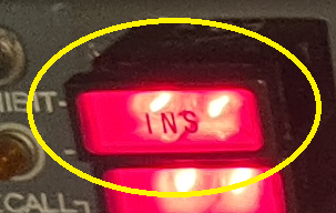
INS (Inertial Navigation System) Loss of inertial information to the AFCS
FEEL Artificial feel failure of any channel
PFC Main jack low pressure or seizure, Inverter failure
STAB Auto-stabiliser total failure in any one axis
XXX Not used
ADS ADS discrepancy
TRIM Electric-trim failure of both channels
SMOKE Smoke detected in rack or underfloor or overfloor hold
NAV Discrepancy in position indicated by INS channels
ADC ADC failure
TRIM Electric trim failure of one channel
AIR Air Condition exchangers overheat

ENG.1 Engine fire or flame detected
ENG.1 Nacelle wing overheat or oil overheat or fire warning failure,
INT.1 Intake system hydraulic failure
ENG.2 ** Turbine cooling air failure or bearing labyrinth temperature
ENG.2 Fire warning sensor failure or oil level high
INT.2 Lane failure
ENG.3 N°1 bearing vibration or low oil pressure
ENG.3 Fuel temperature high or engine anti-ice pressure
INT.3 N 1 fail intake system
ENG.4 Engine wind-down or N° 4 bearing failure
ENG.4 Fuel filter blocked or engine gearbox oil low pressure
INT.4 N 1 reduces or double inverter failure

RADN Excessive radiation detected
FUEL Delivery Pressure low or collector tanks low level or fuel leak,
HYD Pump low pressure, tank low level, tank overheat
PRESS ** Cabin over pressure or altitude excessive
ELEC D.C. or A.C. essential busbar failure
ELEC D.C. or A.C. main busbar failure, battery, TRU, generator failure
THROT Throttle failure
MEPU Fire
N1 RED N1 fail intake system N1 reduce
ICE Ice detected
DOORS Exit, service doors, escape hatch unlocked
OXY
** This caption legend identifying an aircraft system is under realisation by Jean Noel from jnb-maker.com

To enable the flight crew to minimise the possibility of distraction, e.g. during take-off, an INHIBIT push-button switch, on the front face of the panel, enables inhibition of certain class 1 and all class 2 caption lights. Indication of inhibition is given by an amber warning lamp, fitted below the push button.

Illuminated master warning captions should be quickly cancelled to enable other warnings to be received from the same system. Cancellation is achieved by pressing the face of the caption, this open circuits the lamp load and retains the lamp in an extinguished condition, even if the original input signal persists.


Caption lights will automatically extinguish when the fault condition ceases to exist. The associated fault warnings, on the systems management panels, will remain illuminated for the duration of a fault. This ensures that the presence of an uncleared fault, on a system, will always be indicated in the flight compartment when the master warning captions are cancelled.
A RECALL push-button switch, on the front face of the panel, enables crew members to reinstate the illuminations of inhibited captions on all un-cleared faults by pressing the push-button.

Provided that a fault condition still exists, cancelled caption lights can be reinstated by pressing the RECALL push-button, on the display panel. This action produces a signal which is a substitute for the pulse output to the caption light driving circuits. At the same time an output from the recall pulse generator is taken to the alert lights driver to act as an inhibiting signal to the ALERT lights, leaving them in an extinguished state and thus able to operate for any future class 1 red failure warnings.
NOTE: Audio warnings will sound for both red and amber warnings, as applicable, on use of RECALL
Operation
On aircraft 01 and 02, the master warning system is supplied from the 28 - volt D.C. “B” system essential bus bar (4PP), via a circuit breaker on pane 11 - 122, and the 28 - volt D.C. “A” essential bus bar (3PP), via a circuit breaker on panel 1- 122.
End of this voluminous ATA 33 chapter.
Now you must to be patient, because our next technical article will take longer to complete, because it will be devoted to the propulsion system.


Commentaires