
POWERPLANTS ATA 70 – 80. Part 3
- 14 juin 2024
- 4 min de lecture
Before continuing, we must provide important clarification on the difference in the air intake control systems installed on some of the test Concordes and the final version on production aircraft and tested on some test Concordes and particulary the difference between analog and digital.
The original control system was analog like all other Concorde avionics computers. It was manufactured by Ultra, worked on the Concorde prototypes for flights at Mach 2 but required attention and adjustments and more particularly during flights above Mach 2, speeds which were explored during the tests (the record is Mach 2.23 compared to the commercial speed of Mach 2.02). A system more robust to atmospheric variations (temperature vs. pressure) was necessary. After several deliberations, it was decided to develop a digital technology system, at the time of the arrival of the first digital on-board systems in commercial aviation (inertial units in particular) offering a better response with more responsiveness than possible with an analogic system. It was a decision that was taken late in the Concorde program but which was decisive for the performance of Concorde in service. The idea came from the British side (BAC) and the French side (Aérospatiale) was initially opposed to this new idea. This is the first time that a digital system will contribute to a critical system on a civil aircraft.
The system was designed and manufactured entirely by the Guided Weapons department of the British Aircraft Corporation (BAC), based on their new military developments.
The system was installed in August 1972 on the pre-production Concorde 01 G-AXDN in addition to the new Olympus 593 Mk 602 engines which had first been introduced on the Concorde 02 F-WTSA. This had been anticipated because the Concorde 01 had made its first flight in December 1971 with fixed ramps and was limited to Mach 1.5. It returned to service in March 1973 to begin the testing program for this new system.
The Concorde 02, for its part, made its first flight in January 1973 with the old analogic system, a system which he will keep until the end of its flights. This system was, however, usable at Mach 2 and made it possible to transport VIP passengers, notably the first non-stop Atlantic crossing in September 1973 which we recently discussed in an article.
The first production Concorde F-WTSB made its first flight in December 1973 directly with the digital system and therefore contributed to continuing the testing of this system. System which was installed on the following Concordes.
It is this lesser-known analogic system, installed on our SA that we have chosen to present to you.
Now let's start with the part visible in the cockpit of the SA.
The Air Intake Control System (AICS) provides control of variable geometry surfaces in each air intake; These surfaces include a movable front ramp and rear ramps and discharge doors.
The position of the surfaces are automatically adjusted to ensure that satisfactory airflow is provided to the engines at all times and that the intake air flow at the engine does not exceed 0.50 M.
AIR INTAKE CONTROLE ATA 71- 61
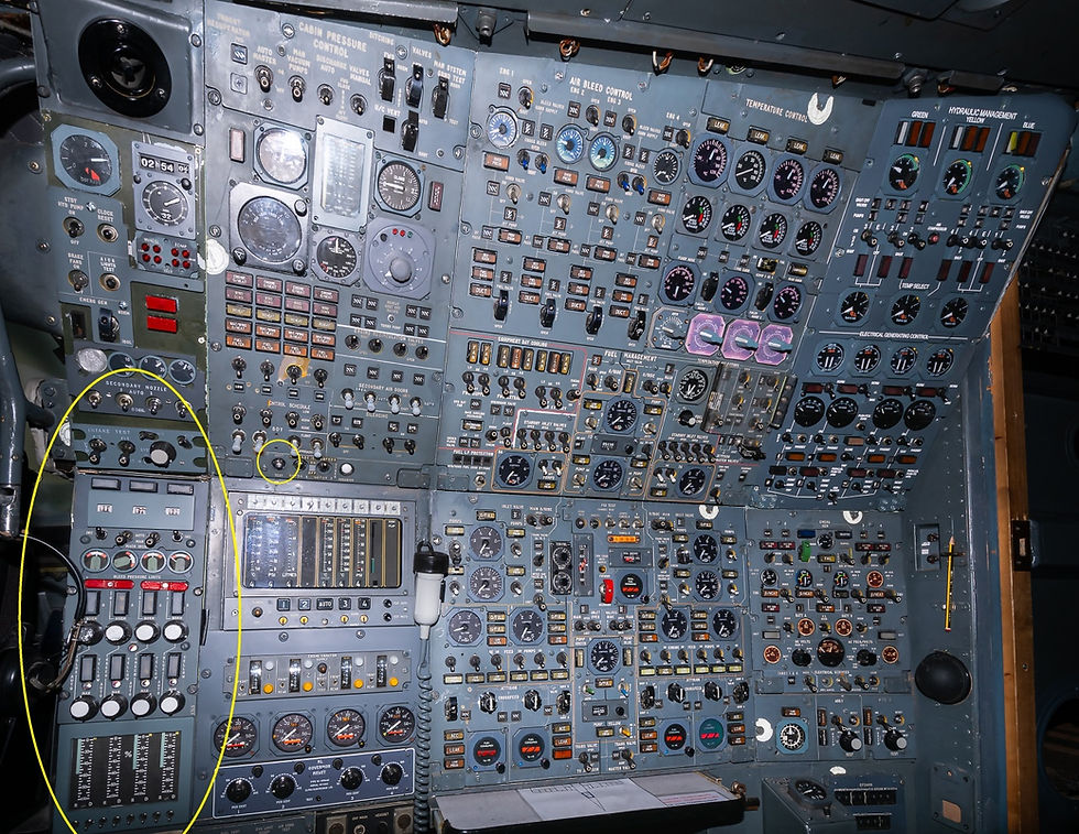
Photo Bertrand LEDUC
The manual control panel (MCP) and the indicators are grouped together on the left-hand side of the third crew member’s management panel and is front-mounted.
Caption and warning light filaments can be checked by the LIGHT TEST push switch.

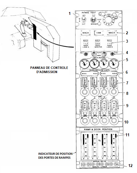


1 Control and Indication
The pre-flight test sequence is controlled from the INTAKE TEST panel which provides:
- A FLT-SYST-BRAKE toggle switch to effect control of the pre-flight test sequence and the ramp actuator brake solenoid tests.
- A SYST-BRAKE warning lamp; illuminated when the FLT-SYST-BRAKE switch is not in the FLT position.
- A twelve-position rotary selector to select the pre-flight test sequence.
- GO and FAIL indicator lamps.
- A HYD A/C-EXT toggle switch to select either the aircraft or external hydraulic supplies for test purposes.


2 Caption lights
Illumination of the YAW caption indicates a sideslip signal failure.

L'allumage de l’indicateur YAW annonce une défaillance du signal.
3 Triplex Mach indicators display:
- The aircraft Mach number.

4 MACH INCHING AUTO-MAN toggle switches provide selection of :
- Automatic or manual Mach inching facilities.
- The adjacent INC toggle switches perform the manual function.le.

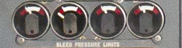
5 The BLEED PRESSURE LIMITS indicators provide a visual monitoring facility of the bleed pressure ratio in each intake.
6 Illumination of the N1SIG captions indicates an engine low pressure compressor speed N1 signal failure.

7 Illumination of the LANE captions indicates a failure in the selected lane.

8 The control lane select switches permit selection of either the main or alternate control lane. The mid-position NORM enables an automatic change over to the alternate lane following a main lane failure.

9 Illumination of the HYD captions indicates a hydraulic failure in the selected system.

10 The hydraulic system select switches permit selection of either automatic or manual operation using the main or alternate systems. The normal position BLUE AUTO and GREEN AUTO permit an automatic a change over to the alternate YELLOW system following a main blue or green system failure.

11The RAMP & DOOR POSITION indicator displays the actual ramp and spill door positions in percentage of travel.
The VANE push button, when held depressed, enables the auxiliary inlet vane positions to be displayed instead of the spill door positions. An electrical supply failure to one or more indication lane is indicated by a black and white diagonal striped panel displayed bene ath the failed indicator lane.

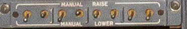
12Three-position toggle switches provide a manual inching facility for each ramp and door :
- MANUAL RAISE
- Centre OFF
- MANUAL LOWER
This panel was missing in the SA cockpit when it arrived at our museum.
For the creation of this panel of which we ensured the final assembly, how greatly benefited from new international cooperation with the help of our friends from:
- DAS (Duxford Aviation Society) who offered us the engraved front plate corresponding exactly to the one originally fitted to the SA.
- Dr Tamas Regert who redesigned the central panel (which was made by laser cutting in Hungary by Sandor and Rudolf), the buttons and indicators which were 3D printed in Holland by a Romanian friend of Tamas.
- Philippe Glei0ze. who made the INTAKE TEST panel.
- The inscriptions on the indicators are still missing but with our friend Jean Noel from https://jnb-maker.com we are looking for the best method to make the engravings.

To be continued…


Commentaires