
SA communication and radio navigation equipment.
- 17 déc. 2020
- 9 min de lecture
In our previous article we discussed the different locations of communication and radio navigation equipment in SA’s equipment bays, those which were, in the shadows, the linchpin of the systems.
Now we'll try to show the tip of the iceberg, the controls and the locations in the cockpit. The same as those on the production Concorde fleet but not always arranged in the same place.


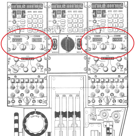
Comparing the “PILOT'S NOTES (Concorde pre-production)” pilot flight manual for the two pre-production aircraft on the left, dating from the start of pre-production flights (1971 for the 01) and this photo of the center console, we can discover some small differences in the arrangement of the controls.
Important note: as we have already mentioned previously SA arrived in Athis devoid of all radio control units and flight instruments. Whenever possible, gaps were filled with genuine Concorde parts, but when this was not, the empty spaces were fitted with equipment performing the same function but from other aircraft.
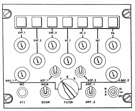
The best example is the Radio Operations Standard. This assembly is designed to allow each of the four crew members (pilot - co-pilot - engineer - first observer) to use all the different radio communication and navigation sub-assemblies installed in the airplane. From the switches, various transmission or listening possibilities are offered to crew members:
transmission on the VHF 1 - VHF 2 - HF 1 - HF 2 - INT - INT CAB
PA channels reception on the channels: VHF 1 - VHF 2 - HF 1 - HF 2 - INT - INT CABIN - P - MARKER NAV 1 (VOR 1 - ILS 1 - DME 1) NAV 2 (VOR 2 - ILS 2 - DME 2) ADF 1 - ADF 2.
Let's start with communication :
No need to explain the imperative for pilots and air navigation controllers to know the exact position of aircraft in terminal areas of airports (especially in low visibility), or in the vastness of the sky above the desert or the ocean.
SA had two types of radios for communication :
The radio control units dedicated to communication are placed on the central console between the pilot and the co-pilot.
VHF (Abbreviation for Very High Frequencies) radio frequencies allocated to communications in civil aviation, with a transceiver used for short and medium range communications. Different sections of the VHF band are also used for air traffic and radio navigation aids.
A priori in SA we only find VHF-1 and VHF-2, each with two frequency display positions, a so-called "active" position and a "preset" position or the frequency just used before.


To save time (as the frequencies are often known in advance) the pilots preselect the next frequency, but as a precaution when they switch to the new one, they keep the previous one in the event that it is impossible to reach the new frequency displayed in order to be able to return on the previous one which was active.
Always taking as reference the PILOT’S NOTES at the location of the VHF-3.


In SA is this reminder of the important geographical coordinates to be inserted in the inertial units during flight tests.

HF (Abbreviation for High Frequencies) Radio transceiver dedicated to very long distance communications.


Due to the need for frequent communications with the test base, SA was provided with 4 HF transceivers accessible to both pilots and the flight engineer, mainly used during flight tests.
Because of the high level of background noise encountered in HF, crews often prefer to reduce the volume of their HF receivers until they are alerted by the SELCAL watch of a sound and light message, which is specifically for them address.
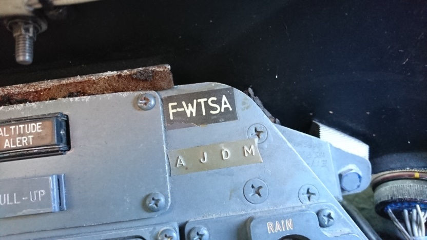
SELAC, (Abbreviation for Selective Calling System) selective calling equipment for radio links. Commercial aircraft equipped with radio are assigned a code (usually a combination of 4 letters) that works for both VHF and HF, so a base station on the ground can come into direct contact with an aircraft through this code.

Below is the code reminder on the dashboard just below the registration reminder.
Let's continue with in-flight identification.
The TRANSPONDER


To help their identification by ground radars, airplanes are fitted with transponders (transmitter – responder). The dials of the transponders range from zero to seven inclusive. The smallest possible code is 0000 and the highest is 7777. There are 4096 possible combinations.
The secondary air traffic control radar transmits an interrogation signal consisting of a coded pulse to which the transponder responds with another coded pulse. The decoded response appears on the ground radar screen in the form of a plot, accompanied by the four-digit code of the aircraft.
By displaying in SA the code 5431 this is what the controller would have seen on his radar screen :

RADAR (acronym for RAdio Detection And Ranging) a very simplified explanation a radar consists of a transmitter associated with a receiver and a display computer. Its operation is based on the principle of echo. The transmitter generates a pulse which like any electromagnetic wave travels through the atmosphere at the speed of light when this pulse hits an obstacle a significant portion of this pulse is reflected and returns to its starting point and visualized on the controller screen.
And now the navigation.
The radios dedicated to radio navigation are placed on the top of the dashboard facing the pilot and the co-pilot on either side of the AFCS and on the dashboard.

VOR (Abbreviation for VHF Omnidirectional Range) is a radio positioning system that works with VHF frequencies.


A VOR radio navigation receiver is used to determine the magnetic bearing of an aircraft relative to a radio station on the ground (VOR transmitter beacon), the position of which is known. The magnetic bearing of an aircraft relative to a VOR is expressed by the radius from the VOR on which the aircraft is located. Each radius from the tag is called a radial. In 90% of cases, a VOR station is coupled to a DME station, thus allowing the aircraft to also know the direct distance which separates it from the VOR-DME. The DME device is explained below.
DME (abbreviation of distance measuring equipment) this distance measuring device is a radio-transponder which allows to know the distance which separates an aircraft from a ground station. The aircraft emits a signal at the beacon frequency entered by the pilot and the beacon sends back a signal on a response frequency with a fixed and precise delay, which allows the aircraft equipment to calculate the time to propagation of the two signals and therefore the distance to the beacon.
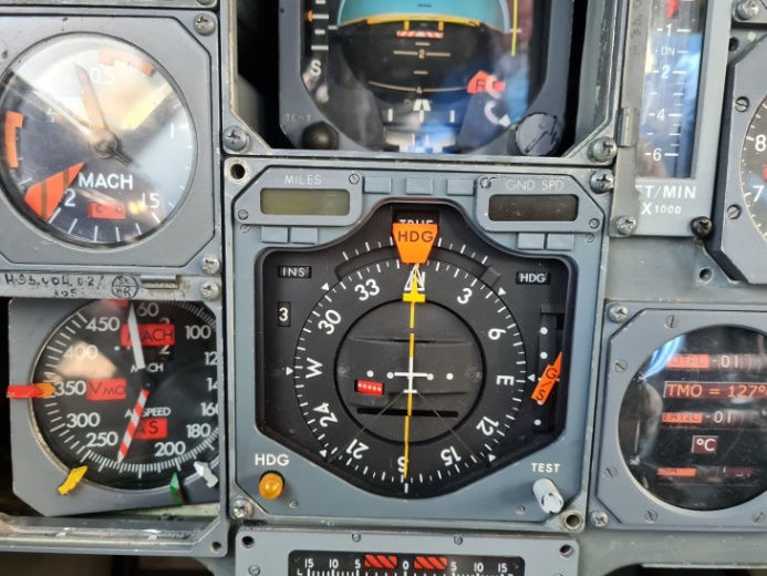
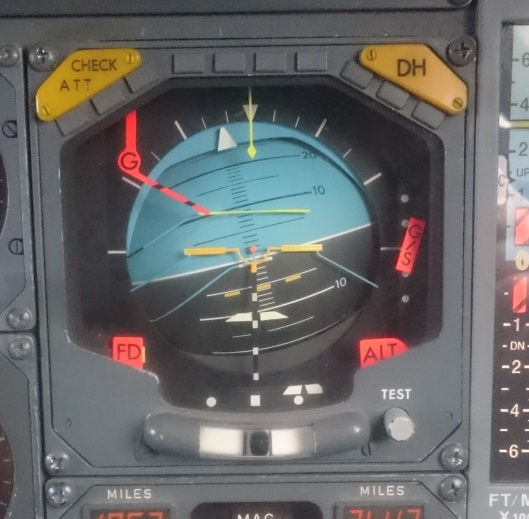
HSI (Abbreviation for Horizontal Situation Indicator) is a horizontal position indicator used in modern airplanes, which brings together several functionalities previously distributed on several instruments. On Concorde, it combines in a single instrument a heading controller, the VOR / ILS indications, the distance indicated by the DME, and the ground speed indicated by the inertial units. The HSI displays either radio-magnetic or inertial information by means of a selector.
Broadly speaking, here are some notable features :
The yellow needle is the route index, which comes from VOR or inertial devices. The white arrow is the heading or course index pre-displayed on the autopilot.
In the center in yellow, the track deviation bar or the ILS radial (runway center line).
On the right, under the G / S flag, is the Glide Slope indicator, indicating during on an ILS approach, the "height" deviation from the vertical approach axis.
Everything is superimposed on a mobile compass rose.
ADF (Abbreviation forAutomatic Direction Finder) A radio compass or direction finder is a radio receiver on board an aircraft allowing it to receive and indicate the direction of beacons or radio beacons in relation to the aircraft and to cardinal points. This receiver has a graduated rose from 0 to 360 ° (compass), on which a needle turns indicating the direction of the station. It is used as a navigation aid.
There are two types of radio beacons on the ground :
the locator: generally located in the axis of a track, it has a reduced range (20 to 50 km)
NDB: used as a navigation aid (see also VOR).
These ground beacons operate in the frequency range 190 to 1750 kHz and are identified by a Morse code.
RMI (Abbreviation for Radio Magnetic indicator) The RMI includes a mobile rose that is automatically reset. Each of the needles can point to an NDB, Locator or VOR depending on what the user has selected.
ADI (Attitude Display Indicator) The attitude indicator, better known under the name of artificial horizon is an on-board instrument that presents part of the piloting information, among others: attitudes, command bars and the number of the flight director, and ILS deviations.
Compared to a classic artificial horizon, in particular, this has two roll and pitch command bars (horizontal and vertical), they are piloted by the selected flight director (automatic pilot).
All these indications are useful for piloting the aircraft, in particular in the case of instrument flight in the absence of an external visual reference, hence its common name of artificial horizon.
For long-distance navigation in aviation, the sextant was used successively for navigation using star position readings, then electronic radio systems, Loran mainly used in the USA and the OMEGA VLF system using eight transmitting stations distributed around the world and using very low frequencies. The VLF system will be replaced by INS system and currently INS coupled with GPS.
INS (Abbreviation for Inertial Navigation System) the inertial unit uses acceleration and rotation sensors to determine the absolute movement of an aircraft, it has the advantage of being completely autonomous. However, it shows a drift in positioning accuracy, which is acceptable for crossing the Atlantic. Concorde was one of the first commercial aircraft to be equipped with INSs. The Apollo program made this technology available at the end of the 1960s. Since the 1990s, inertial units have been coupled with GPS to correct for drift in position. The GPS indicates a precise position every second, but does not have the dynamics (attitudes, speeds) offered by the inertial unit.
The control unit performs several functions transmitted to the autopilot, in particular :
Guidance consists in controlling the trajectory. It makes it possible to follow a reference trajectory, which is materialized by geographical points.
navigation ensures the position, speed and attitude of the aircraft throughout the flight.
By inserting the known geographical points of a route to be followed using the numeric keypad, the control unit informs the AP on the route to be followed by the aircraft, which operates the control surfaces.
Inertial navigation allows navigation between the starting point and the route between it and the current point, and to find the coordinates at any time.
To determine the route to follow SA was equipped with three independent INS systems which are coupled and redundant.


Above the selector allowing choosing which pair of INS feeds the navigation equipment (instruments, AFCS, PA, DV etc.)
Just a word about the AFCS, which is the automatic flight control installation of Concorde, and intended to assume control of the aircraft throughout the flight envelope, since the start of the climb to the landing. But given the importance of this equipment, it will be the subject of a future article.
And to finish the flight properly, you have to land, for that we have the following aids :
ILS (abbreviation for Instrument Landing System), is a landing aid system. It allows a precision approach especially in degraded weather conditions, and provides guidance in the vertical and horizontal plane up to the threshold.
The ILS system includes:
A horizontal guidance called LOCALIZER, allows you to know if you are in the axis of the runway. It emits, thanks to a network of directional antennas located in the extension of the runway, a radio electric beam making it possible to provide the pilot with an indication of horizontal deviation from the runway axis.
Vertical guidance called GLIDE SLOPE (or Glide Path, or Glide), allows you to know if you are descending at the right angle; it emits radio beams in the extension of the runway centreline, providing the pilot with an indication of vertical deviation from the nominal descent slope.
Most of the ILS are coupled with a DME which makes it possible to know the distance to be covered to reach the runway threshold (it represents the 3rd guidance component for a precision approach).
MARKER VHF radio beacon allowing the pilot to determine how far away is the threshold of the runway.
Radio transmitters whose antennas radiate vertically are located all along the approach axis, at varying distances from the threshold. Their role is to inform the pilot of the passage of the aircraft to their vertical and thus to follow the descent path perfectly.
Here is their location on the SA dashboard.


Before ending a little anecdote which was told to us by a friend of the Orly tower controller who had the pleasure of guiding SA for his last landing on May 20, 1976 at 4:26 pm.
Knowing that to perform this 314th and last flight, all the systems and equipment were seriously “lightened”, by touching the runway the braking system was not activated immediately, but thanks to the perfect knowledge of the plane the crew was able to slow down the plane enough to leave the runway at the end, biting "very lightly on the green", which raised a little dust… our controller friend instinctively asked the question "It’s all right?” A short moment later came the calm and collected answer "Now YES ..."

A few minutes later Jean Franchi, Gilbert Defer, Ugo Vercherutti and Claude Durand arriving in front of the Air France hangars, left the Orly ground frequency and definitively cut off everything, engines, radios and SA equipment.
Thank you gentlemen’s ...


Commentaires