
The landing gear - ATA 32 - Part 1
- 25 nov. 2022
- 5 min de lecture
Arriving under the Concorde, we are immediately surprised by the impressive size of the landing gear. Due to the length of the aircraft and its delta wing*, during take-off and landing Concorde will have a higher angle of attack than a conventional aircraft.

Collection AAMD (DR)
The length and the significant nose up of the plane therefore required raising the fuselage with this very high landing gear…
* A bit of history and technique
On July 19, 1867, English inventors James William Butler and Edmund Edwards filed a patent for a steam jet-propelled “delta” wing airplane. However, this wing configuration only really gained momentum in the 1930s, first in France with the prototypes of Nicolas Roland Payen, then in Germany, with the work of Alexander Lippisch.
A delta wing is best suited to high speed flights and in supersonic its shape is close to that of the Mach cone.
The (Cz) maximum lift coefficient of a delta wing is limited by the absence of high-lift devices. This disadvantage is partly offset by the additional lift provided by
- the vortex lift,
- the significant ground effect for a low wing in the nose-up position (the trailing edge being close to the ground and the vertical component of the thrust at take-off).
Given the high angle of attack, to be able to slow down to lower approach speeds Concorde will have to pitch up much more than a conventional aircraft.
In the following articles we will try to show "how it works" and possibly show some differences between the production aircraft and the SA.
The landing gear Concorde is of the electro-hydraulically controlled retractable tricycle type.
It comprises a :
- a nose gear, comprising two wheels mounted in diabolo
Retracts forwards
- two main gears each comprising four wheels mounted in diabolo on a bogie,
Retracts towards the aircraft centre
- a tail bumper comprising two wheels mounted in diabolo,
Retracts to the rear.
Let's start our presentation of this big chapter by visiting the landing gear of the SA.
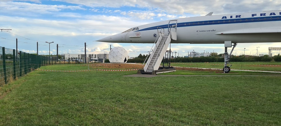
In the background of this picture we can see our new acquisition, the Radom of the Orly tower, the first phase of our project which we talked about in our previous article.
NOSE LANDING GEAR
The nose landing gear is hinged to the aircraft by two lateral bracing struts. The hinge points are located on frame 26 through two lateral bracing struts on which two hydraulic jacks operate allowing the landing gear to retract forward. In the retracted position the doors are closed, restoring the fuselage profile.
A little tour around this big stilt
Both photos show the size of the nose gear during the factory build of the aircraft.
Photos collection AAMD (DR)
 |  |
Gear is on the ground with the hatches closed | On a jack and relaxed shock absorbers |
By comparing the technical documentation between the pre-production aircraft (SA) and the production aircraft, we immediately see the size of the rear hatch and the simplification of its assembly.
 |  |
 |  |
Here is now the front axle of the SA
The two slings are used to hold the aircraft in place on the jack which keeps the wheels out of contact with the ground. The red sheath which will supply electrical current to the radome is fixed there temporarily.
We immediately notice the small tille of the rear hatch.


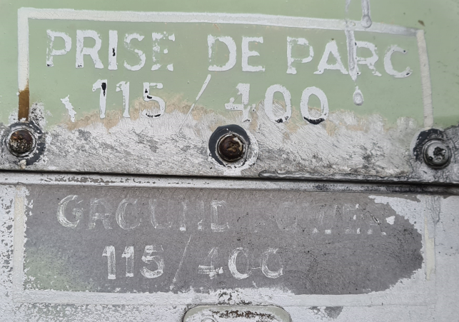
And the special feature that only exists on the SA is a second electric power supply point.
Unlike production aircraft, the two prototypes, and the first pre-production aircraft, the SA has an additional electrical connection of the parking GPU. Located approximately 1.70 m from the ground on right side of the nose gear strut.
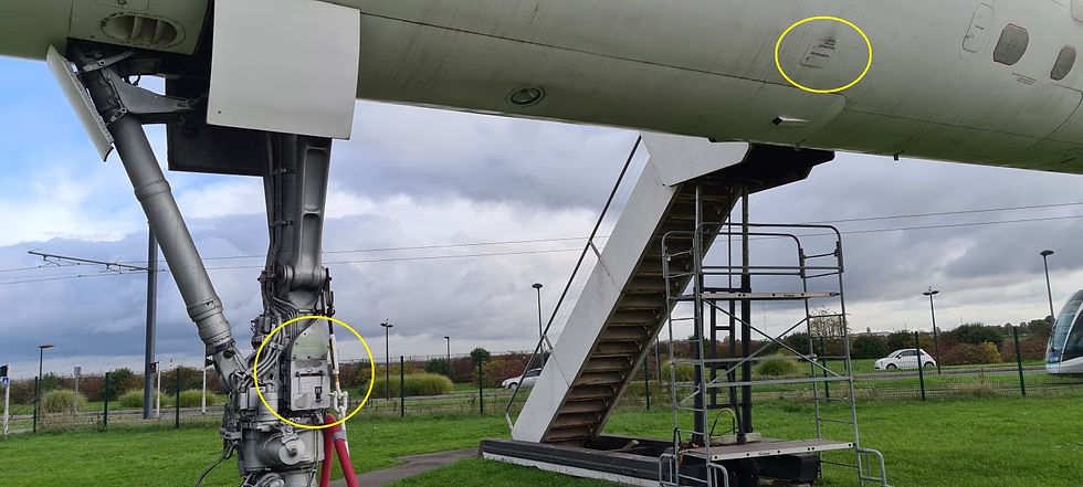
This design was carried out by the engineer Rowland White to allow a ground generator to be connected even in airports which are not equipped with service steps high enough for connection on the right side of the fuselage.
Here an adaptation of a story Rowland shared, with his authorisation.
Rowland was a support engineer for the flight tests in Toulouse, as part of the British team to support systems of BAC’s responsibility:
“During visits to airports with F-WTSS, and early visits with F-WTSA, the airport ground crews were often not prepared for the location of the Electrical Ground Power receptacle on the aircraft. This was on fuselage - as it “always is” on an airliner. However, with the short nose landing gear of conventional aircraft this is easy to reach. Concorde’s long nose leg meant the ground support crew needed a ladder to connect the power. Many airports were not prepared for this, and often there was considerable delay whilst someone went to search for a suitable ladder.
In appearance, F-WTSA was the most production-like of the first batch of aircraft, and it soon began a series of visits which highlighted this issue. Consequently, Aerospatiale decided to add a second ground power receptacle on the nose landing gear! This was not a simple matter, as by definition this gear moves, contracts, folds etc. Additionally, they had to position the receptacle not to get blocked or showered with snow, ice or heavy rain. Since electrical power supply was a BAC responsibility, the task of engineering fell to Rowland, supported by his draftsman (“Pete”), who had to produce the detailed drawings of Rowland's scheme. This modification has never been ever consider for the production aircraft, due to the addition of totally unnecessary weight.
Design considerations:
The first issue, rather obviously, is that whatever they designed had to not impede the function of the landing gear, including retraction. This also meant that the cables could not extend to, or beyond the oleo. It made sense therefore, to fit the receptacle at the bottom of the nose leg, above the steering unit. They would make a machined aluminium enclosure, and it would be on the right hand side of the gear, facing right. This orientation and location would mean that the receptacle was “on the same side” as the existing fuselage receptacle (which they would leave fully functional). Additionally it would not face directly forwards, protecting it from debris and weather during take-off and landing. However, the cables would need to run up the front of the nose leg, in order to be clear of potential contact with any metalwork especially when closed. Therefore a system of protective shrouds were designed to ensure the cables remained protected at all times.”
The photographs illustrate the final arrangement.


In addition, some images showing the connection of the ground power unit at the very beginning of the flight tests before the modification described by Mr White.

And after the modification during the “extreme cold” tests in Gander and Fairbanks.

Photos collection AAMD (DR)


And during endurance flights, departing from Roissy/CDG.
We sincerely thank Mr. White for his contribution to our article.
But that's not all …
In our next articles, we will talk about the steering system and the emergency exit of the nose gear, the main gear and the auxiliary tail gear.


Commentaires