The landing gear ATA 32 Part 3
- 27 janv. 2023
- 4 min de lecture
Editor's note: Initially our intention was to compare and show “all the differences” between the pre-production aircraft 01 and our SA and later the production aircraft, but due to lack of documentation or the visual inaccessibility of the elements we will limit ourselves to just to which we can show by picture and confirm with documentation in our possession.
Let's continue our visit with this impressive main landing gear.
The Hispano-Suiza Company was entrusted with the study and construction of the main landing gear by providing specific solutions:
- Materials used: 186hb high resistance steel structure.
- Kinematics: retraction of 10% (more than 4m height) of the undercarriage leg being raised
- Reliability: design of “FAIL-SAFE” character assemblies and use of solutions that have proven themselves in service, such as the internal locking system that has paid several million movements on the Caravelle in commercial operation.
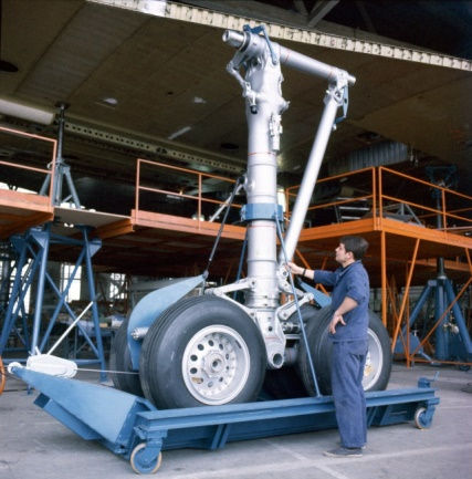
Collection AAMD (DR)
Its size puts the lower part of the fuselage at this surprising height, which could allow the majority of vehicles to pass under the fuselage without difficulty compared to all other conventional aircraft. Of course, the reason for this size was mentioned at the beginning of this series of articles.
These images show the right landing gear of the SA which rests on jacks fixed to the concrete slab and two tie rods fixed to the upper part of the landing gear to ensure the fixing of the plane to the ground.
Note that some of Kleber Colombes tires are still those used during last flight tests and the delivery flight between Toulouse and Orly on May 20, 1976.
Main Landing Gear and Doors
Main Gear
Each main gear is mounted in the wing spar vessel between ribs 21 and 22, and pivoted between on a crossbeam and operated by a suspended hydraulic jack. Articulation is effected by a hinge beam to which the leg and fixed strut is attached. The ends of the hinge beam are housed in two self-aligning bearings attached to the wing structure in line with rib 21 A. Landing gear operation is ensured by a hydraulic actuating jack.
In the retracted position the doors are closed, restoring the wing and fuselage profile.
The main landing gear is realised of 30 NCD I6 forged steel.
It's constituted of:
· A leg,
· A cross beam,
· A fixed drag brace,
The whole forms a rigid triangle.

An oleo pneumatic shock absorber, which slides inside the leg. Partially housed in the landing gear leg, it directly provides damping and lift functions.

This drawing shows the section of the main shock absorber on the left in the relaxed position and on the right in the compressed position.
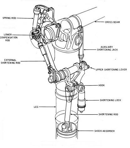
When you don't have enough space to accommodate the landing gear in the fuselage, the engineers have found an ingenious solution to shorten the shock absorber.
First the main shock absorber compresses and rises by 508 mm, then a shortening device further reduces the length of the landing gear leg by 15 mm the shock absorber assisted by a hydraulic cylinder, the device allows the wheels to stop as soon as that the main doors are in the open position.
And here is on the SA the only visible part of the whole system, protected by a fine fishing net to prevent pigeons from installing their nests "well sheltered".
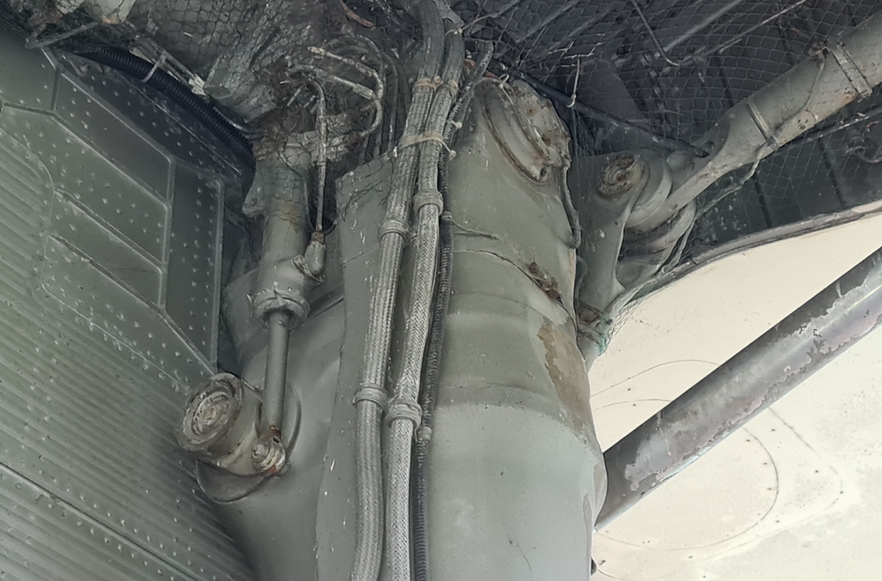
A bogie balancer,
Articulated at the bottom of the shock absorber, supports the wheel spindles.
It is attached to the bottom end of the shock-absorber. At each end of the bogie beam is a hole which takes the axle for each pair of twin wheels. At each extremity of the bogie are yokes to take the pitch damper end fittings, and which also carry ball adapters for jacking the twin wheels.

Two torque links
Linked to the bottom of the shock absorber, keep the bogie parallel to the axis of the plane.
They are attached by the upper arm to the bottom end of the leg forging and by the lower arm to the bottom part of the shock absorber sliding tube. The torque links re-transmit the vertical moment torque due to a dissymmetry of force or pivoting on the wheels, and retransmits the movement to the leg and the crossbeam.
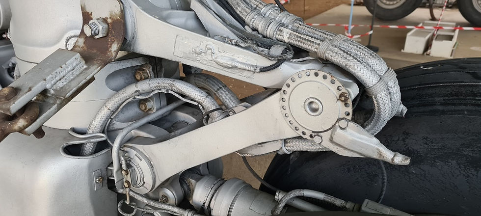
Compas avant

Compas arrière
Two oleo-pneumatic shock absorbers,
They made it possible to absorb all the irregularities of the ground during rolling and to ensure the orthogonal positioning of the rocker arm in relation to the axis of the leg, both during the lifting maneuver and in the retracted gear position. If one shock absorber is completely deflated, the other is capable of performing the required function on its own. These double effect shock absorbers (compression and traction) allow a longitudinal travel of ± 19° of the bogie arm.

Located above the bogie and on either side of the strut, ensure a
- In flight: the perpendicular of the bogie, in relation to the leg.
- When driving: the damping of oscillations,
Only one of the two shock absorbers is sufficient to perform these functions (fail safe system).
At one end they are attached to the sliding tube and at the other to the brake torque plates. They re-transmit the braking loads to the sliding tube and all the leg structure.

Four brake bars:
Identical, fixed on the one hand to the sliding tube and on the other hand to the brake torque plates, transmit the braking forces to the sliding tube and to the entire structure of the leg.
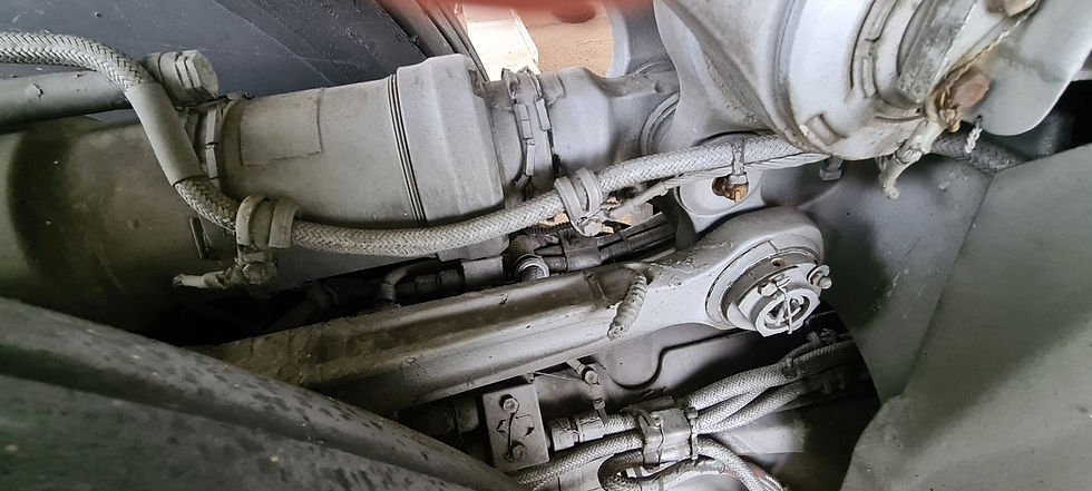
A lifting point and an attachment point for the desludging system.
We can see on the inner side this casing, which houses the hydraulic and electrical accessories connexion that make the link between the upper part and the lower part of the main landing gear.
The metal casings are to be removed quickly (Side Fairing).
To be continued…




Commentaires