The landing gear - ATA 32 Part 5
- 30 mars 2023
- 5 min de lecture
Before continuing an important clarification on the L/G lowering manoeuvres that we talked about in our precedent article.
The "SUPERSONIC FLIGHT" safety functions on the normal system.
Above M 0.95 the visor must be high. This configuration is used to ensure safety in supersonic flight, on the normal L/G system. This safety function causes the decompression of the normal gear circuit. Manoeuvring landing gears with the visor up is therefore made impossible.

Let's now return to the base of the main landing gear and the wheels, and continue our visit.
THE WHEELS

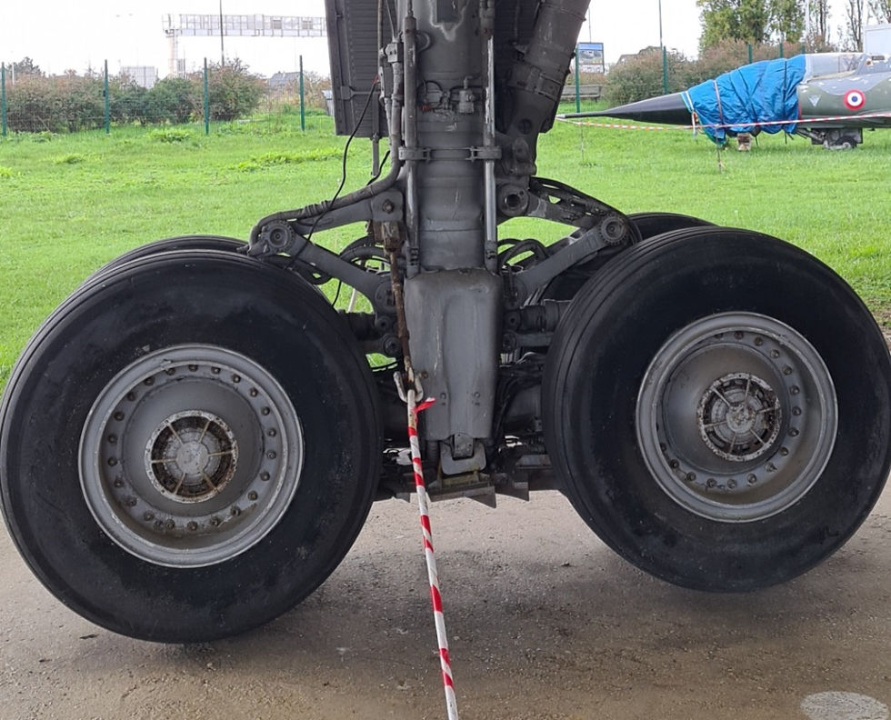
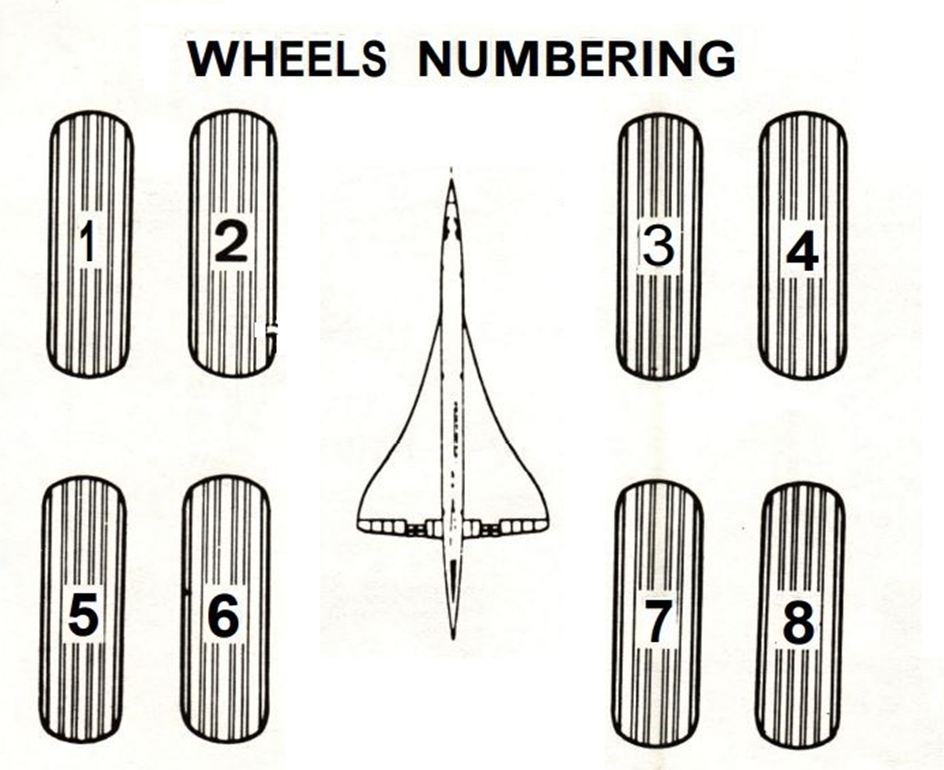
The main landing gear has eight wheels.

Wheels are fitted with taper roller bearings and rotate on the axles. They are provided with a system that deflates the tyre in the case of overheating so preventing it from bursting.
As we can still see today, SA was equipped with KLEBER tires during flight tests and during its last flight May 20 1976 to Orly.

Below is an advertisement that adorned the wall of the garage that maintained Mr. PAYEN's car in Athis Mons, as Mr. GUIEGUIN promised him, he will offer the poster to the Delta Museum when his garage closes where it is now on display.

THE BRAKES
Above the entire brake block which alone would require a complete article, we will talk about it briefly a little further down.

But the main innovation brought to commercial aviation by Concorde and in particular by the SA is the development of the braking system with Carbon discs in 1975.
BRAKING SYSTEM CONTOL
Only the main landing gear wheels have a braking system which is controlled by the pilots. The system offers three types of braking; NORMAL, EMERGENCY and PARKING, selected by a lever on the centre pedestal.

NORMAL
Normal braking is controlled by the rudder pedals. It is proportional and differential. Pressure is supplied by the GREEN hydraulic system, replaced in the case off a failure by the YELLOW system. In both instances, an electronic regulating system (SPAD) based on the comparison of the speed of the nose and main wheels, prevents the wheels from locking. The force feel proportioned toped al pressure is supplied by the internal spring at each transmitter, the return sprig of each pedal, and the effect of the control pressure resulting from the compressing of the emergency distributor springs.
EMERGENCY
Emergency braking, proportional and differential, without electronic regulation, is controlled by the rudder pedals which act on a self-contained hydraulic system. The latter ensures transmission of pedal movements to the braking distributor. The force feel at the pedals is restored in the same manner as for normal braking control. Hydraulic services are ensured by the YELLOW hydraulic system, or by a YELLOW emergency accumulator.
The accumulator can be pressurized by an electric pump.
PARKING
Parking braking, supplied by the YELLOW hydraulic system or by the YELLOW emergency accumulator, is controlled by the braking select lever. Braking in this instance is maximum on the main landing gear brakes.
This brake is used in the park position (cold brakes) before the start but will only be used for the time necessary to put the chocks in place (hot brakes) to prevent them from locking up.
Concorde is equipped, for braking, with a SPAD system (advanced anti-slip system) to control slip, that is to say the difference in speed between braked wheels and unbraced wheels. This system reduces stopping distances by 15% on dry ground and improves safety on wet ground. The braking system Is electrically controlled.
The brake discs are made of ventilated carbon, which offer a mass saving of 500 kg compared to steel discs, as well as better resistance to overheating.
CARBON BRAKES
Stopping a mass of several hundred tons launched at a hundred km/h is not an easy task.
Carbon brakes offer significant advantages over previous generation brake systems. Indeed, carbon offers better performance both hot and cold and can withstand temperatures of up to several thousand degrees. Its performance is such that it saves material compared to other materials. This also allows a weight gain of up to several hundred kilograms per aircraft. Carbon is also more durable and resists better over time; a carbon brake lasts on average three times longer than a steel brake.
Carbone brakes are located in the centre of the wheels of each main landing gear. The brake discs are stacked on top of each other and placed in the centre of the wheels, half is fixed to the rim of the wheel and rotates with it and the other half is fixed to the leg of the landing gear and therefore remains fixed, the discs are thus mounted alternately.
During braking, the discs are compressed against each other by pistons mounted at one end of the stack of brake discs which act first on a disc integral with the landing gear, which then compresses the other discs of the system of brake. Only half of the pistons are normally used, the other pistons being reserved in case the first half fails.
Editor's note: As we cannot show you here the brakes of the SA and which was equipped during the flight tests and on its arrival at Orly on May 20, 1976 with KLEBER tires. Here is a superb presentation of this Carbon wheels and brake set at the Sinsheim Technik Museum.
A museum to visit absolutely several times, not only for Concorde but for everything else presented.
Wikipedia source:
Concorde undercarriage landing gear and brake assembly consisting of twin Michelin wheels and Dunlop carbon disc brakes with SNECMA SPAD anti-lock braking units.
The tyres were specially developed for the Concorde by Michelin to endure the extreme strain and temperature differences during take-off, landing and supersonic flight. The tyres shown here are new and unused.

You MUST read the article by Pierre GRANGE on MICHELIN tires.
On the APCOS website: https://www.concordereference.fr/le-pneu-michelin-nzg
Another innovation used on Concorde, ventilation (cooling) of the braking system.
The tightening of the brake discs causes very significant overheating which can even in certain cases cause the tires to burst.
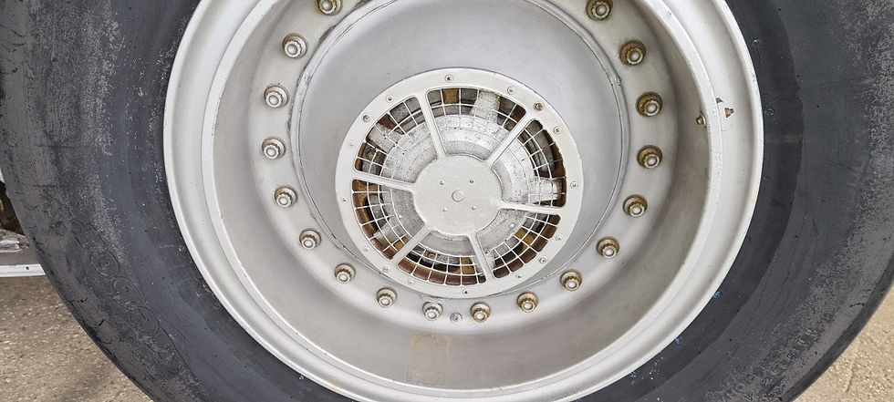
To avoid excessive heating, a ventilation system is mounted in the central part of the spindle of each wheel via a tubular support.

A plate screwed at the end of the tube retains the motor; the electrical outlet disconnects automatically. Removing the generator requires removing the wheel and the threaded end of the spindle which is held therein by peripheral studs.
Ventilation is provided by a turbine, driven by an electric motor. The air is extracted from the wheel, after passing between the wheel and the heat sink, and through ventilation holes made in the fabric. A sheet metal casing covers the rim, ensuring the channelling of the air. A gridprotects the turbine.


To be a little more complete in a few lines, another interesting function on Concorde.
BRAKING ON RETRACTION
In addition, automatic braking is assured for the main and nose landing gear wheels during the landing gear retraction sequence.
Braking control on retraction of the main landing gear wheels is achieved by means of the electrical braking system. This control is automatic. Braking on retraction of the nose landing gear wheels is achieved by an automatic hydraulic control, as described previously.
This braking occurs under the following conditions: The brake selector lever is at "NORMAL". After the aircraft has taken off, the landing gear selector lever is at UP. This position controls: the power supply to one of the two solenoids in the braking electro-valve which feeds hydraulic pressure to the servo-valves.
The closure of the pedal - position transmitter relays which short-circuit the potentiometers for each servo-valve through a fixed resistance. This resistance acts on the pedal-position transmitters to provide a constant current to the second coil in the servo-valve. The servo-valve then delivers hydraulic pressure at approximately 1450psi (100 bars) to the brakes.
NOTE: Pilot action on the pedals no longer has any effect on the braking. At the end of the landing gear door-opening sequence and directly the landing gear locked down relay moves in to the rest position, the electro-valve is no longer energized; it closes, cutting off hydraulic pressure to the servo-valves and, consequently to the brakes.
To be continued…


Commentaires